Three-dimensional direct-welding blade assembly welding system of steam turbine

A direct-welded, blade set technology, applied in the field of steam turbines, can solve the problems of low work efficiency, difficult to control precision, and dimension deviation of the throat of the steam passage, and achieve the effects of improving work efficiency, easy operation and improving assembly accuracy.

Active Publication Date: 2011-09-14
QINGDAO JIENENG STEAM TURBINE GROUP CO LTD
View PDF0 Cites 0 Cited by
  • Summary
  • Abstract
  • Description
  • Claims
  • Application Information

AI Technical Summary

Problems solved by technology

[0008] The scribing method commonly used at present has the disadvantages of difficult control of precision and low work efficiency.
The scribing method is mainly human-controlled for the installation angle and pitch of the three-dimensional static blade assembly. The assembly accuracy depends on the technical level of the operator. The size measurement is observed with the naked eye using tools such as a board ruler and tape measure, which is difficult to guarantee the measurement accuracy. In this case, the latter blade needs to be based on the installation position of the previous blade, which can easily cause error accumulation and cause the size deviation of the throat of the steam passage
The scribing method is all manual operation, the adjustment of the spatial position of the partition body and the outer ring of the partition, the positioning of the inlet and outlet sides of the stator blades on the partition body and the outer ring are cumbersome, and the work efficiency is low

Method used


Image

  • Three-dimensional direct-welding blade assembly welding system of steam turbine
  • Three-dimensional direct-welding blade assembly welding system of steam turbine
  • Three-dimensional direct-welding blade assembly welding system of steam turbine

Examples


Embodiment Construction

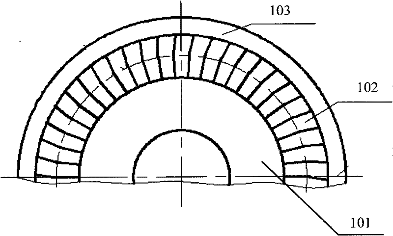
[0043] The invention discloses a three-dimensional direct-welding blade assembly welding system for a steam turbine to ensure the determination of the three-dimensional space positions of the three-dimensional stationary blade, the partition board body and the partition outer ring.

[0044] The following will clearly and completely describe the technical solutions in the embodiments of the present invention with reference to the accompanying drawings in the embodiments of the present invention. Obviously, the described embodiments are only some, not all, embodiments of the present invention. Based on the embodiments of the present invention, all other embodiments obtained by persons of ordinary skill in the art without making creative efforts belong to the protection scope of the present invention.

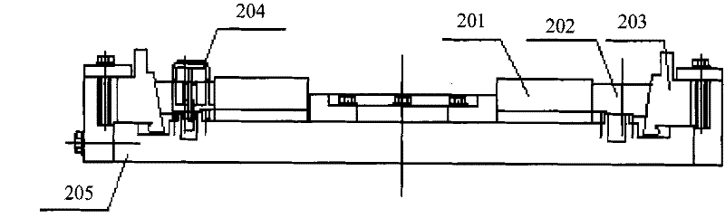
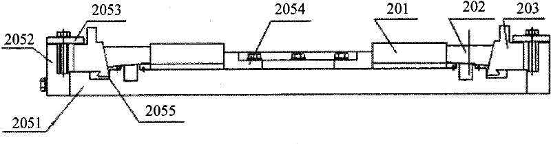
[0045] see Figure 2-Figure 5 , figure 2Schematic diagram of the structure of the positioning mold used in conjunction with the installation angle clamp provided by the embodime...


PUM


Abstract

The invention discloses a three-dimensional direct-welding blade assembly welding system of a steam turbine, which is used for determining the three-dimensional space positions of stator blades, a diaphragm body and a diaphragm outer ring in a direct-welding welded diaphragm and comprises a positioning mould and an installation angle fixture, wherein the positioning mould is provided with a firstpositioning reference surface used for limiting the space position of the diaphragm body and a second positioning reference surface used for limiting the space position of the diaphragm outer ring; the positioning mould is provided with positioning bodies for controlling the pitch of each stator blade; and the installation angle fixture is used for limiting the space position of each stator blade. The invention can accurately control the space positions of the diaphragm body, the diaphragm outer ring and the three-dimensional stator blades; the pitch of each stator blade is controlled by a set of corresponding positioning bodies; errors are complementary, and the error accumulation is not formed, and therefore, the assembling precision is greatly improved. The installation angle fixture can accurately control the installation angle and the trailing edge height of each stator blade and does not need a tool to measure.

Description

technical field [0001] The invention relates to the technical field of steam turbines, more specifically, to a three-dimensional direct welding blade assembly welding system for steam turbines. Background technique [0002] With the rapid development of computer technology and computational fluid dynamics, the flow design of steam turbine has leaped from the two-dimensional era to the full three-dimensional era. Nowadays, the flow design technologies of steam turbines in all countries in the world are based on 3D-NS calculation and analysis. The 3D-NS calculation analysis of multiple schemes has successfully developed advanced dynamic and static three-dimensional curved blades. The blade effectively improves the working efficiency of the steam turbine, and is highly valued and developed and utilized by fluid industries such as steam turbines. Such as figure 1 As shown, the stator blade 102 is actually the nozzle for the steam turbine to perform work. It is a channel with ...

Claims


Application Information

Patent Timeline
Patent Type & Authority Patents(China)
IPC IPC(8): B23K37/04B23K37/053
Inventor 程联忠刘刚黄义福
Owner QINGDAO JIENENG STEAM TURBINE GROUP CO LTD
Why Eureka
Try Eureka