Self-sealing transfusion valve component and plug valve and socket valve thereof

A self-sealing, infusion valve technology, applied in the direction of valve devices, functional valve types, engine components, etc., can solve the problems of low liquid temperature, no liquid filling work, inconvenient application, etc.

Active Publication Date: 2011-01-05
HENAN AEROSPACE HYDRAULIC & PNEUMATIC TECH
View PDF3 Cites 2 Cited by
  • Summary
  • Abstract
  • Description
  • Claims
  • Application Information

AI Technical Summary

Problems solved by technology

[0002] Due to work loss, the liquid working medium in the machine with liquid working medium will decrease with the increase of working time, which requires replenishing the liquid medium in the machine. At present, there is no special tool to complete the work of adding liquid. Under normal circumstances, people generally choose to directly pour the working fluid placed in the container into the liquid storage tank of the machine. If the opening of the liquid storage tank is small, they usually use a tool with one end open and the other end small to open the machine. The small opening end of the tool is inserted into the opening of the liquid storage tank, and the working fluid is poured into the large opening end of the tool. This method is simple but inconvenient, especially not suitable for use in dusty and dusty environments. , when the amount of working fluid is large, this method of adding liquid is clumsy and time-consuming, and the application is very inconvenient. At the same time, if, in a low temperature environment, this way of directly adding liquid will make the temperature of the liquid too low, so that Affect

Method used


Image

  • Self-sealing transfusion valve component and plug valve and socket valve thereof
  • Self-sealing transfusion valve component and plug valve and socket valve thereof
  • Self-sealing transfusion valve component and plug valve and socket valve thereof

Examples


Embodiment Construction

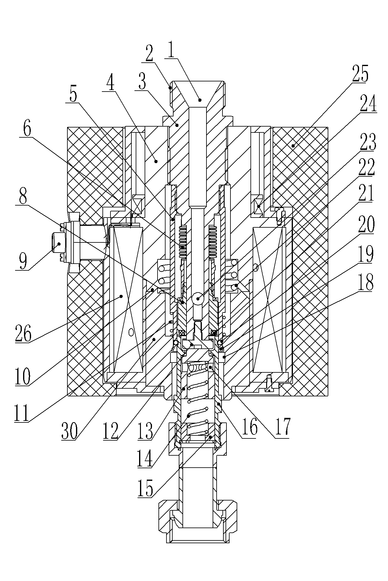
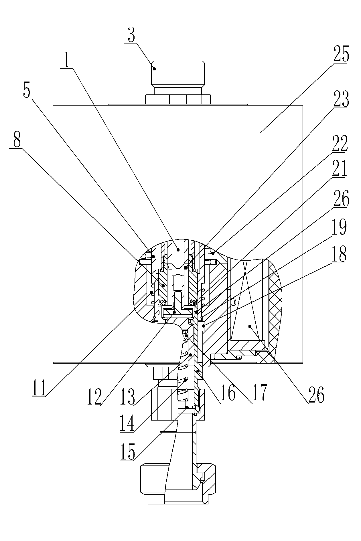
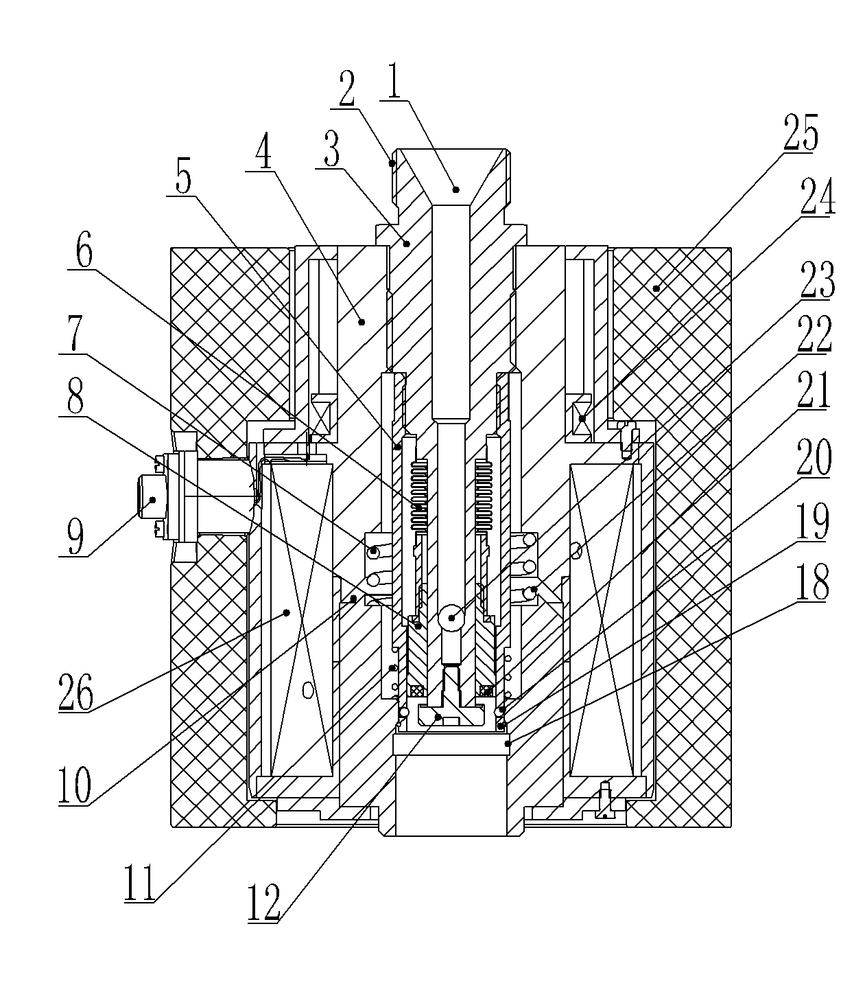
[0022] An embodiment of a self-sealing infusion valve assembly, in figure 1 , 2 in, combine image 3 and Figure 4, the infusion valve assembly includes a socket valve and a plug valve. Hole 1, the front end of the through hole 1 has an internal thread, and a sealing disc 12 is screwed through the thread, the sealing disc 12 seals the front end of the through hole 1, and the front part of the through hole 1 has a wall extending from the wall of the through hole 1 to the socket valve The radial hole 23 on the outer wall of the part 3, the socket valve part 3 is a circular tube, and its front end has two parallel planes extending backward from the front end to the rear of the radial hole 23. The front part of the socket valve part 3 is slidingly sleeved with a self-sealing tube 8, and the rear end of the self-sealing tube 8 is in sealing cooperation with the part after the radial hole 23 of the socket valve part 3. Since the front section of the socket valve part 3 has a cut-...


PUM


Abstract

The invention relates to a self-sealing transfusion valve component and a plug valve and a socket valve thereof. A seal-sealing pipe is hermetically sleeved on the front part of a socket valve piece of the socket valve in a sliding way; the back end of the self-sealing pipe is in elastic fit with a push step surface of the socket valve piece; a seal disc of which the back end is matched with an inner ring of a sealing ring on the front end face of the self-sealing pipe is fixed at the front end of the socket valve piece; the socket valve piece is provided with a valve port channel communicated with the front port of the seal-sealing pipe; a connecting lock sleeve fixed with the socket valve piece is sleeved on the outer side of the seal-sealing pipe; a lock cylinder is radially assembled on the sleeve wall of the connecting lock sleeve in a sliding way; an unlocking sleeve is sleeved on the lock cylinder on the outer side of the connecting lock sleeve in a sliding and limiting way; the back end of the unlocking sleeve is in press fit with the connecting lock sleeve through a return spring; the periphery of a socket valve body of the socket valve is provided with a lock groove; thefront end of an inner hole of the socket valve body is provided with a valve seat; a valve plate is assembled in the inner hole of the socket valve body in a sliding way; the back end of the valve plate is in elastic fit with the socket valve body; the front end of the socket valve body is provided with a press pipe projecting forwards; and the valve plate is provided with a push head extending forwards out of the valve seat.

Description

technical field [0001] The invention relates to an infusion valve assembly for transferring liquid from one container to another container, and the invention also relates to a plug valve and a socket valve of the infusion valve assembly. Background technique [0002] Due to work loss, the liquid working medium in the machine with liquid working medium will decrease with the increase of working time, which requires replenishing the liquid medium in the machine. At present, there is no special tool to complete the work of adding liquid. Under normal circumstances, people generally choose to directly pour the working fluid placed in the container into the liquid storage tank of the machine. If the opening of the liquid storage tank is small, they usually use a tool with one end open and the other end small to open the machine. The small opening end of the tool is inserted into the opening of the liquid storage tank, and the working fluid is poured into the large opening end of ...

Claims


Application Information

Patent Timeline
Patent Type & Authority Applications(China)
IPC IPC(8): F16K21/04
Inventor 胡丽敏刘刚陈丹燕高汉平毋会卿庞晓丽刘洪霞邵真贵
Owner HENAN AEROSPACE HYDRAULIC & PNEUMATIC TECH
Why Eureka
Try Eureka