
FTTH (Fiber To The Home) optical fiber junction terminal box

A technology of optical fiber connection and terminal box, applied in the direction of fiber mechanical structure, etc., can solve the problems of inaccessible, high construction cost, large volume, etc., and achieve the effect of solving the connection problem, reducing the use cost, and making the connection simple and fast

Inactive Publication Date: 2011-01-05
昆山市大唐通讯设备有限公司
View PDF0 Cites 2 Cited by
  • Summary
  • Abstract
  • Description
  • Claims
  • Application Information

AI Technical Summary

Problems solved by technology

The current method is to use an optical cable terminal box to complete the connection between the two. However, the existing facilities are too large to be accommodated in the FTTH multimedia box, and the user's optical cable terminal box is a box body that adopts a thermal fusion method. , resulting in inconvenient connection of equipment, inconvenient connection of optical fiber and high construction cost

Method used


Image

  • FTTH (Fiber To The Home) optical fiber junction terminal box
  • FTTH (Fiber To The Home) optical fiber junction terminal box
  • FTTH (Fiber To The Home) optical fiber junction terminal box

Examples


Embodiment Construction

[0031] The specific implementation manner of the FTTH optical fiber connection terminal box of the present invention is given below with reference to the accompanying drawings.

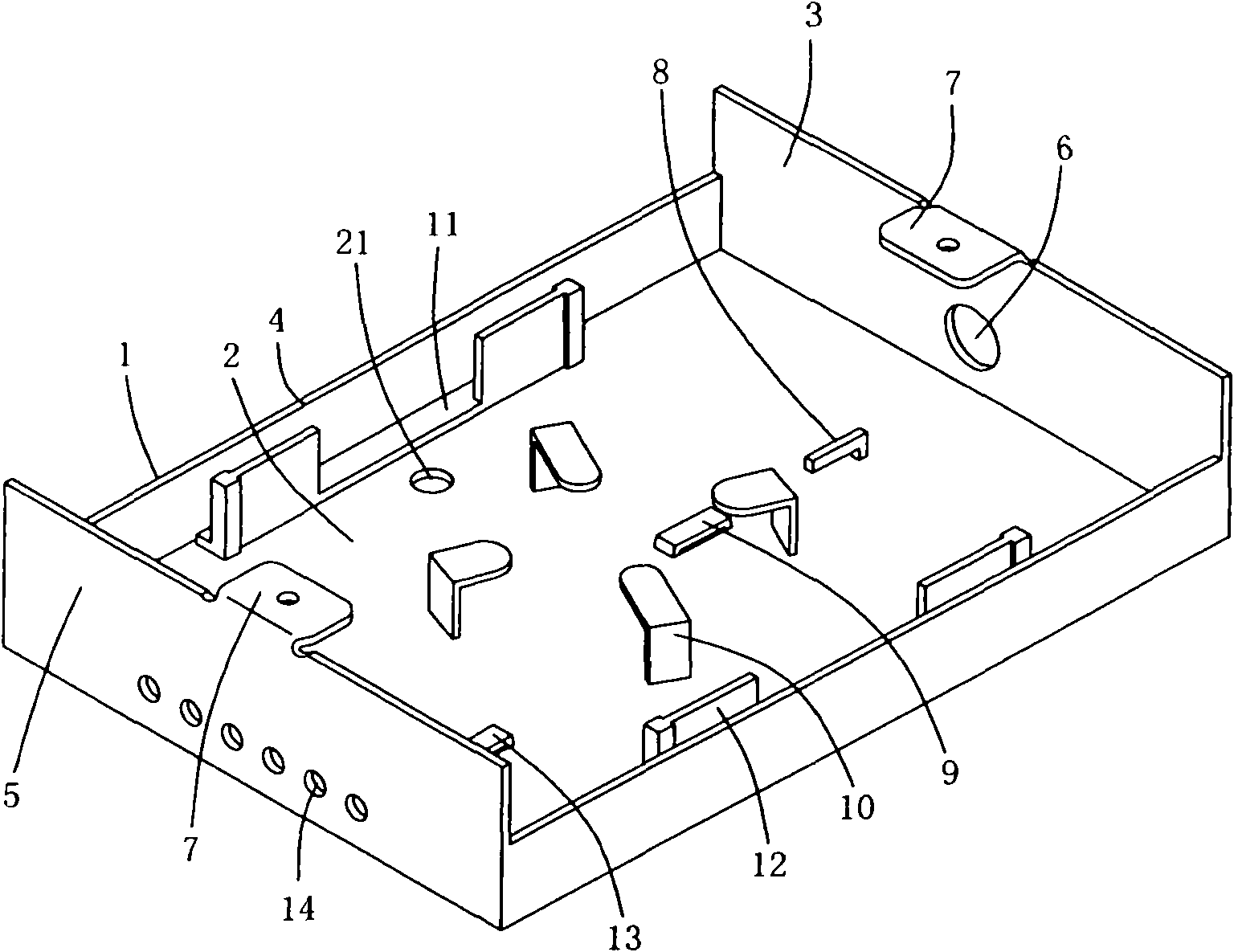
[0032] See attached figure 1 , Schematic diagram of the structure of the FTTH optical fiber connection terminal box.

[0033] An FTTH optical fiber connection terminal box adopts a box body 1 with a bottom plate 2, a front plate 3, a side panel 4, and a rear plate 5. The box body 1 can be made of metal materials and is equipped with a box cover. The front plate 3 of the box body 1 And the middle of the upper end of back plate 5 is provided with lid fixed support 7, and lid fixed support 7 is provided with thread connecting hole, and box cover is connected on the box cover fixed support 7 by screw connecting hole.

[0034] An outdoor optical cable lead-in hole 6 is set in the middle of the front plate 3 of the box body 1, and a plastic ferrule is embedded in the outdoor optical cable lead-in hole 6, w...


PUM


Abstract

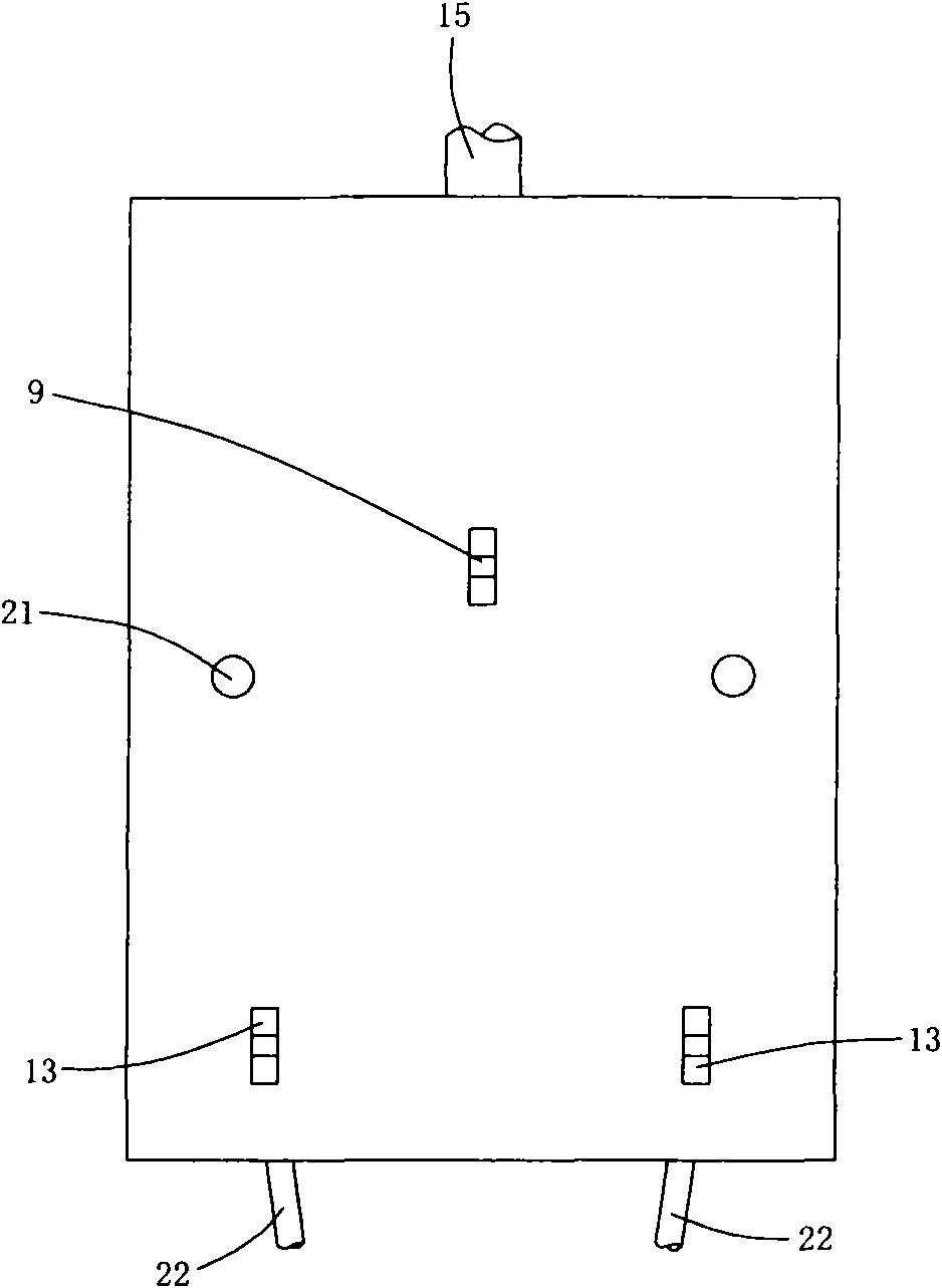
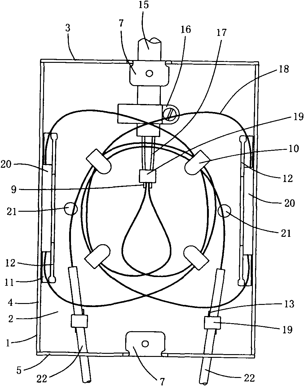
The invention relates to an FTTH optical fiber junction terminal box. The front end of a box body is provided with an outdoor optical cable lead-in hole; a bottom plate below the lead-in hole is provided with an outdoor optical cable fixing nail and an optical fiber beam tube fixing nail; the middle of the bottom plate is provided with a fiber coiling rack; the inner sides of a left panel and a right panel are provided with cold connector fixing slots; the rear end of the box body is provided with an optical fiber output port and an output optical fiber fixing nail; an outdoor optical cable enters the box body through the lead-in hole and is fixed on the fixing nail through a stainless steel tube hoop; an optical fiber beam tube is fixed on the optical fiber beam tube fixing nail; a bare optical fiber is coiled in the fiber coiling rack and is respectively coiled to cold connectors in the left cold connector fixing slot and the right cold connector fixing slot; an output optical fiber is led into the box body through the optical fiber lead-in hole and is fixed; the bare optical fiber of the output fiber is coiled in the fiber coiling rack and is coiled to the cold connectors; and the cold connectors are connected with the outdoor cable and the output optical fiber. The invention has the advantages that the FTTH optical fiber junction terminal box can be accommodated in an FTTH multimedia box body, can well fix the outdoor optical cable and conveniently uses the optical fiber rapid cold connectors, thereby the use cost is obviously reduced and the equipment maintenance is more convenient.

Description

【Technical field】 [0001] The invention relates to the technical field of optical fiber communication equipment, in particular to a fiber-to-the-home FTTH optical fiber connection terminal box. 【Background technique】 [0002] In the urban communication network, the application of optical fiber technology is developing very fast, and the scope of application is becoming wider and wider. In addition to regional backbone optical cables, fiber to the community (FTTP) and fiber to the home (FTTH) are developing rapidly. In cities, especially in large and medium-sized cities, the offices of governments and enterprises have basically realized informatization and automation. Connecting outdoor optical cables to office buildings or residential quarters, or even residents' homes, is to be distributed and connected through a series of optical fibers. Optical fiber distribution equipment includes the connection, splicing and line adjustment between the main optical cable in the optical ...

Claims


Application Information

Patent Timeline
Patent Type & Authority Applications(China)
IPC IPC(8): G02B6/44
Inventor 蔡志祥杨钧奎
Owner 昆山市大唐通讯设备有限公司
Learn More