Light emitting diode driving method

A technology of light-emitting diodes and driving methods, which is applied to instruments, static indicators, etc., can solve the problems of low luminous efficiency, concentrated current consumption, energy loss and temperature rise of light-emitting diodes, so as to achieve uniform current consumption and reduce energy consumption. loss, reducing the effect of cross-voltage loss

Active Publication Date: 2011-01-05
AU OPTRONICS CORP
View PDF5 Cites 6 Cited by
  • Summary
  • Abstract
  • Description
  • Claims
  • Application Information

AI Technical Summary

Problems solved by technology

[0004] However, for the LED backlight module in the prior art, there will be the following situations: (1) The current value of the driving current of the LED is fixed at the highest gray scale current, and if the highest gray scale current is used when the brightness is not the highest gray scale, it will Make th

Method used


Image

  • Light emitting diode driving method
  • Light emitting diode driving method
  • Light emitting diode driving method

Examples


Embodiment Construction

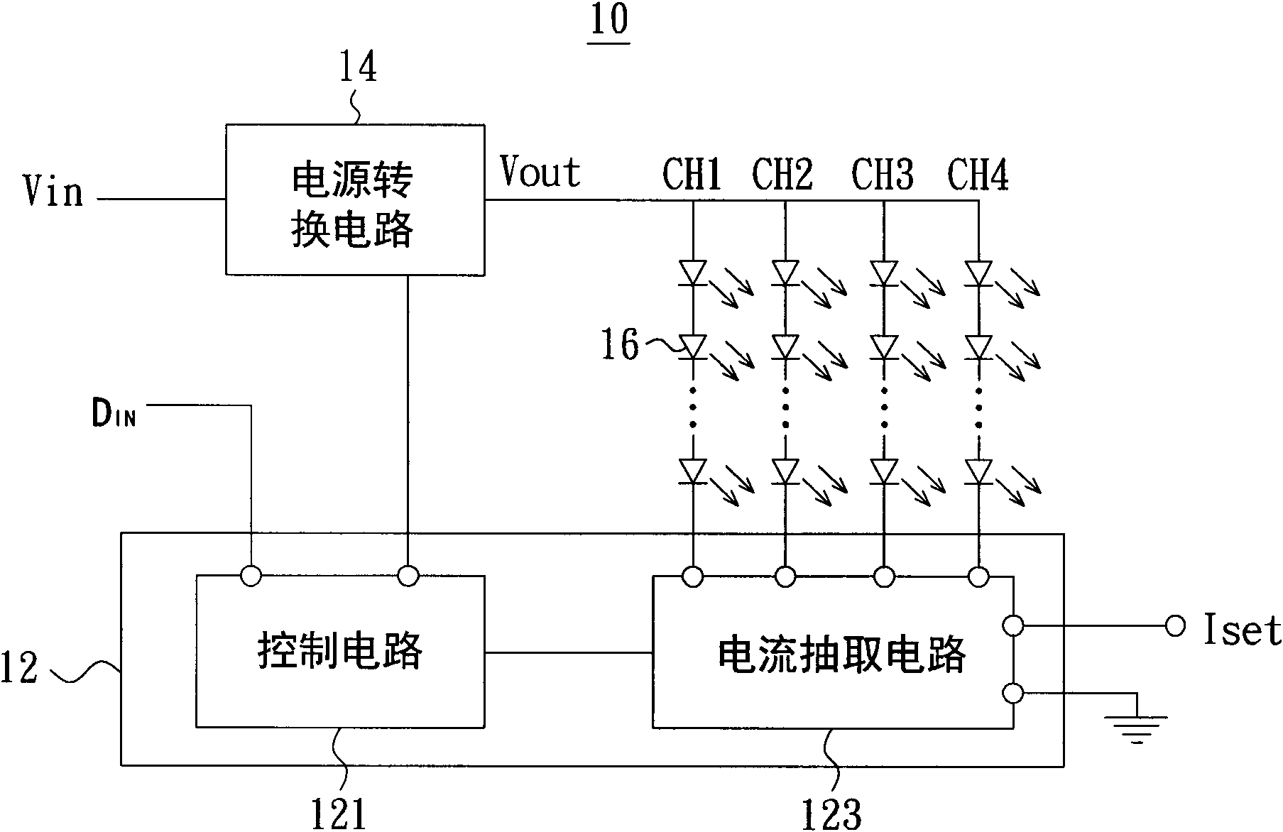
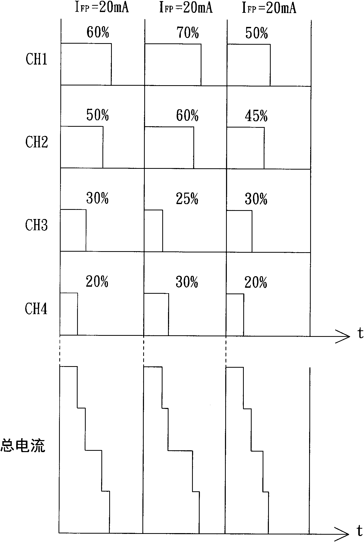
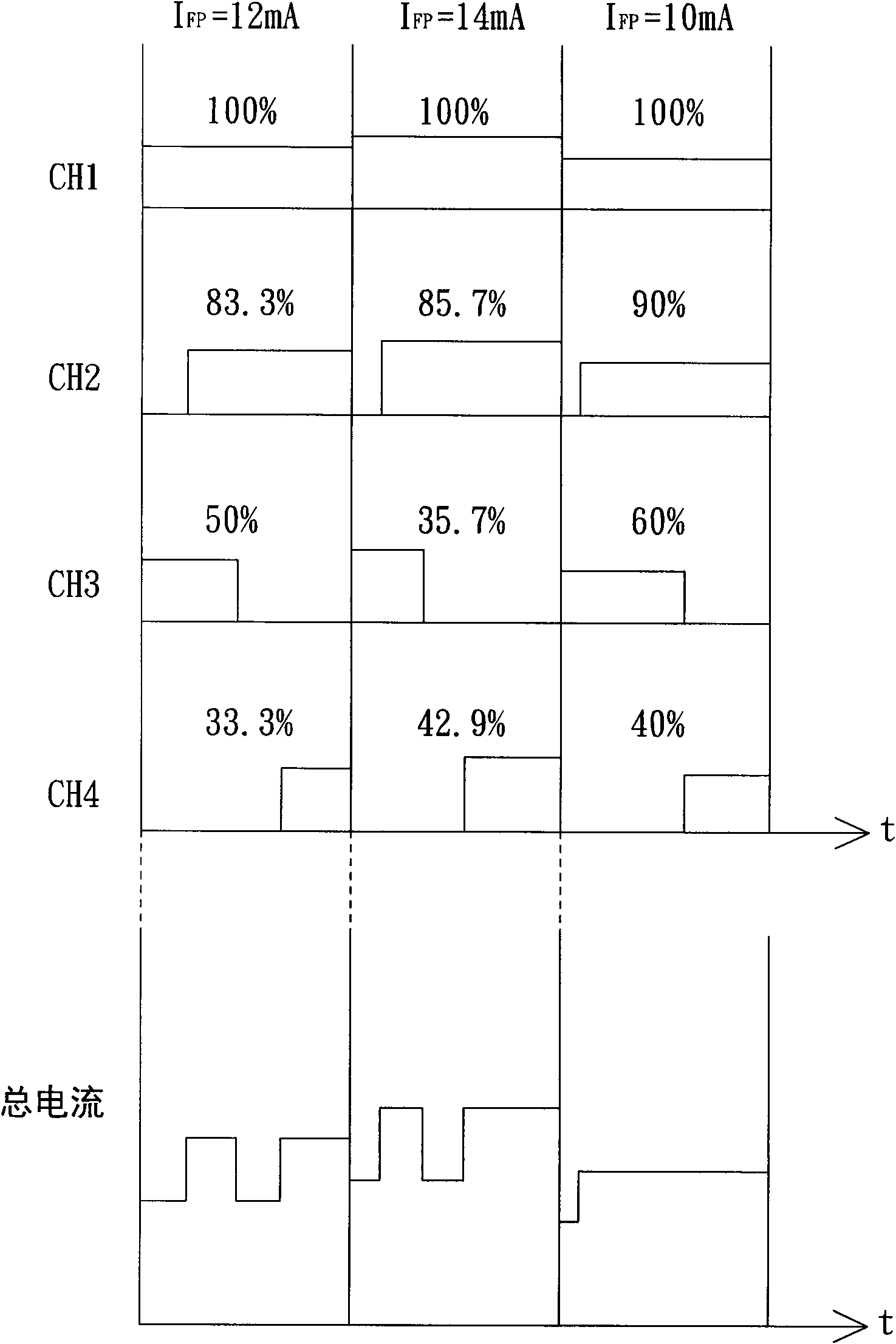
[0028] see image 3 , which shows a schematic diagram of the state of the driving current of each LED string when performing local dimming in an LED driving method related to an embodiment of the present invention. Here, it should be noted that the light emitting diode driving method in the embodiment of the present invention can also be implemented in figure 1 For the LED backlight module shown, the designer only needs to increase figure 1 The functions of the control circuit 121 and the current extraction circuit 123 are enough, so that the control circuit 121 has the function of adjusting the duty cycle of the driving current of each LED string such as CH1~CH4 within the frequency cycle, and the current extraction circuit 123 has the function of adjusting The current value of the driving current of each LED string CH1-CH4 within the frequency period.

[0029] The following will combine figure 2 and image 3 The method for driving a light emitting diode according to an ...


PUM


Abstract

The invention relates to a light emitting diode driving method, suitable for driving a plurality of light emitting diode strings. Each light emitting diode string comprises a light emitting diode or a plurality of light emitting diodes connected in series. The light emitting diode driving method comprises the following steps of: acquiring the initial duty ratio of the driving current of each light emitting diode string in a frequency cycle so as to acquire the target accumulated glow brightness of each light emitting diode string; when the maximum value of the initial duty ratios of the driving currents of the light emitting diode strings in the frequency cycle is smaller than the frequency cycle, extending the duty cycle of the driving current of each light emitting diode string in the frequency cycle and enabling the accumulated brightness of the light emitting diode string in the extended duty cycle to be equal to the target accumulated glow brightness.

Description

technical field [0001] The invention relates to the technical field of driving light emitting diodes, and in particular to a driving method of light emitting diodes. Background technique [0002] For non-self-illuminating displays, for example, the display panel of a liquid crystal display does not emit light itself, so a backlight source is needed to provide backlighting for the display panel. At present, backlight sources can be roughly classified into cold cathode fluorescent lamps, hot cathode fluorescent lamps, light emitting diodes (LEDs) or other electroluminescent elements. Among them, light-emitting diodes are more and more widely used as backlight sources for liquid crystal displays due to their advantages such as high color saturation, no mercury, long life, low energy consumption, and adjustable color temperature through driving current. [0003] see figure 1 and figure 2 ,in figure 1 A structural block diagram of a light-emitting diode backlight module in t...

Claims


Application Information

Patent Timeline
IPC IPC(8): G09G3/34
Inventor 王登科李弘庆余景州
Owner AU OPTRONICS CORP
Why Eureka
Try Eureka