LED constant current drive circuit and LED light fixture

A constant current drive and circuit technology, applied in the direction of electric lamp circuit layout, electric light source, lighting device, etc., can solve the problems of low efficiency, large loss, and increase the complexity of the circuit, so as to achieve a simple circuit structure, improve overall efficiency, and reduce energy. The effect of loss

Inactive Publication Date: 2013-12-04
OCEANS KING LIGHTING SCI&TECH CO LTD +1
View PDF3 Cites 5 Cited by
  • Summary
  • Abstract
  • Description
  • Claims
  • Application Information

AI Technical Summary

Problems solved by technology

Because the input voltage is mostly AC 220V mains, if the resistive step-down method is directly used to supply power to the PWM chip, the loss will be large and the efficiency will be low. Therefore, the auxiliary winding is used to supply power to the PWM chip most of the time, but the auxiliary winding Genera

Method used


Image

  • LED constant current drive circuit and LED light fixture
  • LED constant current drive circuit and LED light fixture

Examples


Example Embodiment

[0019] The technical solutions in the embodiments of the present invention will be clearly and completely described below in conjunction with the accompanying drawings in the embodiments of the present invention. Obviously, the described embodiments are only a part of the embodiments of the present invention, rather than all the embodiments. Based on the embodiments of the present invention, all other embodiments obtained by those of ordinary skill in the art without creative work shall fall within the protection scope of the present invention.
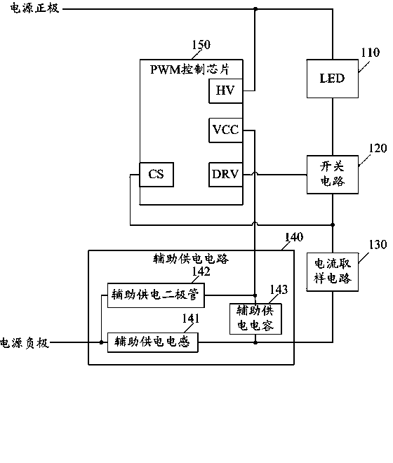
[0020] See figure 1 , Is a schematic diagram of the structure of the LED constant current drive circuit provided by the present invention, including LED 110, switch circuit 120, current sampling circuit 130, auxiliary power supply circuit 140 and PWM control chip 150, auxiliary power supply circuit 140 includes auxiliary power supply inductor 141, auxiliary power supply Diode 142 and auxiliary power supply capacitor 143. The LED 110, the...


PUM


Abstract

The embodiments of the invention disclose an LED constant current drive circuit and an LED light fixture. The LED constant current drive circuit comprises an LED, a switch circuit, a current sampling circuit, an auxiliary power supply circuit and an PWM control chip, wherein the auxiliary power supply circuit comprises an auxiliary power supply inductor, an auxiliary power supply diode and an auxiliary power supply capacitor; the LED, the switch circuit, the current sampling circuit and the auxiliary power supply inductor are successively series connected and then are connected between the anode of a power supply and the cathode of the power supply; the starting end of the PWM control chip is communicated with the anode of the power supply; the power supply end of the PWM control chip is communicated with the cathode of the power supply through the reverse auxiliary power supply diode, and is communicated with the cathode of the power supply successively through the auxiliary power supply capacitor and the auxiliary power supply inductor; the pulse output end of the PWM control chip is communicated with the control end of the switch circuit; and the feedback control end of the PWM control chip is connected with the current sampling circuit. By using the LED constant current drive circuit and the LED light fixture, energy consumption can be reduced and efficiency can be improved.

Description

technical field [0001] The invention relates to the field of lamp drive, in particular to an LED constant current drive circuit and an LED lamp. Background technique [0002] With the continuous development of science and technology, new products and new technologies are constantly innovating. As an emerging light source, LED has the characteristics of energy saving, environmental protection and high efficiency. LED technology has matured and is used in various fields. In order to prolong the service life of LED and improve the stability of LED In LED lamps, a constant current drive circuit is usually used to drive the LED to emit light. [0003] According to the topology, the current LED constant current drive circuit can include BUCK, BOOST, forward, flyback and other combined circuits. Because the input voltage is mostly AC 220V mains, if the resistive step-down method is directly used to supply power to the PWM chip, the loss will be large and the efficiency will be low...

Claims


Application Information

Patent Timeline
IPC IPC(8): H05B37/02
Inventor 周明杰黎晶
Owner OCEANS KING LIGHTING SCI&TECH CO LTD
Why Eureka
Try Eureka