[0026] The present invention will be described in further detail below in conjunction with the accompanying drawings.
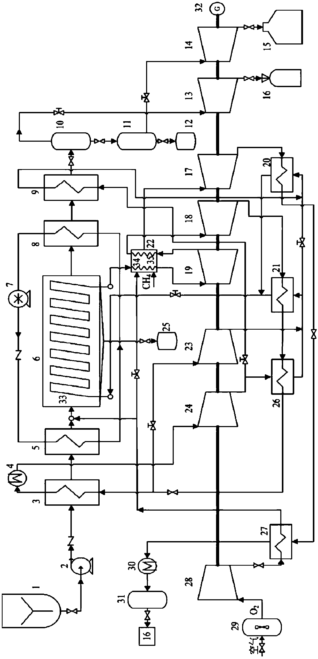
[0027] Such as figure 1 As shown, the power generation system of coal supercritical hydrothermal combustion and supercritical carbon dioxide cycle coupling includes a coal supercritical hydrothermal combustion reaction system, a supercritical carbon dioxide cycle power generation system and an auxiliary heating system.
[0028] The coal supercritical hydrothermal combustion system includes a coal water slurry storage tank 1, a high pressure coal water slurry pump 2, a first heat exchanger 3, a second heat exchanger 5, a supercritical hydrothermal combustion reactor 6, and a circulating water pump 7. The third heat exchanger 8, the fourth heat exchanger 9, the carbon dioxide separator 10, the particulate separator 11, the particulate collector 12, the gas turbine 13, the hydraulic turbine 14, the waste liquid treatment device 15, the carbon dioxide capture device 16 , Oxygen preheater 27, oxygen compressor 28, air separation device 29; the outlet of coal water slurry storage tank 1 is connected with the inlet of high pressure coal water slurry pump 2, the outlet of air separation device 29 is connected with the inlet of oxygen compressor 28, and the oxygen The outlet of the compressor 28 is connected to the inlet of the low temperature side of the oxygen preheater 27, the outlet of the high pressure coal water slurry pump 2 is connected to the inlet of the low temperature side of the first heat exchanger 3, and the outlet of the low temperature side of the first heat exchanger 3 communicates with the second heat exchange The low-temperature side inlet of the second heat exchanger 5 is connected, and the low-temperature side outlet of the second heat exchanger 5 and the low-temperature side outlet of the oxygen preheater 27 are connected with the fuel side inlet of the supercritical hydrothermal combustion reactor 6, and the supercritical hydrothermal combustion reactor 6 fuels The side outlet is connected with the high temperature side inlet of the third heat exchanger 8, the high temperature side outlet of the third heat exchanger 8 is connected with the high temperature side inlet of the fourth heat exchanger 9, and the high temperature side outlet of the fourth heat exchanger 9 is connected with the carbon dioxide separator 10 is connected to the inlet, the gas phase side outlet of the carbon dioxide separator 10 is connected to the inlet of the gas turbine 13, the gas turbine 13 outlet is connected to the carbon dioxide capture device 16, and the liquid phase side outlet of the carbon dioxide separator 10 is connected to the inlet of the particulate separator 11 The outlet on the liquid phase side of the particulate separator 11 is connected with the inlet of the water turbine 14, the outlet of the water turbine 14 is connected with the waste liquid treatment device 15, the outlet on the solid side of the particulate separator 11 is connected with the particulate collection device 12, and the second heat exchanger 5 The high temperature side and the low temperature side of the third heat exchanger 8 are connected with the circulating water pump 7 to form a circulating water circuit, and the ash generated during the coal combustion process falls into the ash collector 25.
[0029] The supercritical carbon dioxide cycle power generation system includes a cooler 4, a first heating surface 33, a second heating surface 34, a third heating surface 35, a carbon dioxide low pressure turbine 18, a carbon dioxide high pressure turbine 19, a fifth heat exchanger 20, and a high temperature return Heater 21, recompressor 23, main compressor 24, low-temperature regenerator 26, generator 32; the outlet working fluid of the first heating surface 33 is superheated by the second heating surface 34 in the methane combustion chamber 22 and then interacts with the high-pressure carbon dioxide turbine 19 The inlet is connected, the outlet of the carbon dioxide high-pressure turbine 19 is reheated by the third heating surface 35 in the methane combustion chamber 22 and then connected to the inlet of the low-pressure turbine 18, and the outlet of the low-pressure turbine 18 is connected to the high-temperature side inlet of the high-temperature regenerator 21 The high-temperature side outlet of the high-temperature regenerator 21 communicates with the high-temperature side inlet of the low-temperature regenerator 26, and the high-temperature side outlet of the low-temperature regenerator 26 communicates with the high-temperature side inlet of the first heat exchanger 3 and the inlet of the recompressor 23, The carbon dioxide at the high-temperature side outlet of the first heat exchanger 3 is cooled by the cooler 4 and enters the main compressor 24. The outlet of the main compressor 24 is connected with the low-temperature side inlet of the low-temperature regenerator 26 and the low-temperature side inlet of the fourth heat exchanger 9. The low temperature side outlet of the regenerator 26 communicates with the low temperature side inlet of the high temperature regenerator 21 and the low temperature side inlet of the fifth heat exchanger 20, and the low temperature side outlet of the fourth heat exchanger 9 communicates with the low temperature side inlet of the fifth heat exchanger 20 , The low-temperature side outlet of the fifth heat exchanger 20 and the low-temperature side outlet of the high-temperature regenerator 21 communicate with the inlet of the first heating surface 33. The generator 32 is connected to the water turbine 14.
[0030] The auxiliary heating system includes a gas turbine 17, a methane combustion chamber 22, a condenser 30, and a carbon dioxide separator 31; the inlet of the methane combustion chamber 22 is connected to the outlet of the low temperature side of the oxygen preheater 27, and the flue gas after the combustion of methane and oxygen is sent to the gas turbine 17, The outlet of the gas turbine 17 communicates with the high temperature side inlet of the fifth heat exchanger 20, the high temperature side outlet of the fifth heat exchanger 20 communicates with the high temperature side inlet of the oxygen preheater 27, the high temperature side outlet of the oxygen preheater 27 and the condenser 30 inlet The outlet of the condenser 30 is communicated with the inlet of the carbon dioxide separator 31, and the outlet of the carbon dioxide separator 31 is communicated with the carbon dioxide capture device 16.
[0031] The supercritical carbon dioxide cycle power generation system is coupled with the coal supercritical hydrothermal combustion reaction system and the auxiliary heating system through the supercritical hydrothermal combustion reactor 6 and the methane combustion chamber 22 respectively.
[0032] The oxygen compressor 28, the main compressor 24, the recompressor 23, the high pressure turbine 19, the low pressure turbine 18, the gas turbine 17, the water turbine 14, the gas turbine 13, and the generator 32 are arranged coaxially.
[0033] The circulating water in the circulating water system is feed water for traditional thermal power boilers. The coal water slurry is converted to standard coal according to the calorific value, and the mass concentration of standard coal is not less than 35wt%. Both the cooler 4 and the condenser 30 are cooled by cooling water.
[0034] The first heating surface 33 is arranged in the supercritical hydrothermal combustion reactor 6 through convection and radiation to absorb coal combustion and release heat. The second heating surface 34 and the third heating surface 35 are arranged in the methane combustion chamber 22 through convection and radiation. Radiation absorbs the heat of combustion of methane.
[0035] Using coal supercritical hydrothermal combustion to release heat as the main heat source, the coal water slurry is pumped from the outlet of the coal water slurry storage tank 1 through the coal water slurry pump 2, the first heat exchanger 3, and the second heat exchanger 5 into the supercritical The flue gas is generated by combustion in the hydrothermal combustion reactor 6, and the flue gas at the outlet of the supercritical hydrothermal combustion reactor 6 is cooled by the circulating water in the third heat exchanger 8 and the supercritical carbon dioxide in the fourth heat exchanger 9 in turn. The supercritical water in the flue gas is cooled into liquid water. The carbon dioxide in the flue gas is separated by the carbon dioxide separator 10 and sent to the gas turbine 13 for work. After the pressure energy is recovered, it is sent to the carbon dioxide capture device 16 for capture, and the carbon dioxide separator 10 separates it. After the particles are removed by the particle separator 11, the liquid enters the hydraulic turbine 14 to perform work. After the pressure energy is released, the liquid is processed by the waste liquid treatment device 15 for recycling.
[0036] The supercritical carbon dioxide cycle uses the methane combustor 22 for overheating and primary reheating on the basis of the recompression layout, and uses supercritical carbon dioxide at the outlet of the main compressor 24 to recover the waste heat of coal-fired flue gas, and uses it at the low temperature side inlet of the high temperature regenerator 21 The supercritical carbon dioxide is split to recover the waste heat of the flue gas of the gas turbine 17, and the low-temperature side outlet of the low-temperature regenerator 26 adopts the supercritical carbon dioxide to split, and the branch flow to the main compressor 24 first preheats the coal water slurry and then enters the cooler 4.
[0037] Using methane combustion as an auxiliary heat source, the flue gas generated after the methane enters the combustion chamber 22 and emits heat enters the gas turbine 17 to perform work. The exhaust gas of the gas turbine 17 is sequentially cooled by the fifth heat exchanger 20, oxygen preheater 27, and condenser 30. The carbon dioxide in the flue gas is separated by the carbon dioxide separator 31 and sent to the carbon dioxide capture device 16.
[0038] The air passes through the air separation device 29 to obtain oxygen. After the oxygen enters the oxygen compressor 28 for compression, it is further preheated by the oxygen preheater 27, split at the outlet of the oxygen preheater 27, and leads all the way to the supercritical hydrothermal combustion reactor 6. , All the way to the combustion chamber 22.
[0039] In the specific operation of the power generation system, the coal water slurry is boosted from the storage tank 1 by the high pressure coal water slurry pump 2 to 25MPa, and then preheated to 300°C by the first heat exchanger 3 and the third heat exchanger 5, and then injected Supercritical hydrothermal combustion reactor 6. After the oxygen is produced by the air separation device 29, it is compressed to 25MPa by the oxygen compressor 28, and the oxygen preheater 27 is preheated to 300°C, and then sent to the supercritical hydrothermal combustion reactor 6. Coal and oxygen undergo a combustion reaction in the supercritical hydrothermal combustion reactor 6 to release heat, and the temperature in the supercritical hydrothermal combustion reactor 6 is 650-700°C. The ash generated in the coal combustion process is collected by the ash collector 25 after sedimentation. After the combustion flue gas is cooled by the circulating water through the third heat exchanger 8, it enters the fourth heat exchanger 9 and is cooled by the supercritical carbon dioxide branch flow. The supercritical water in the flue gas is transformed into liquid water. Then, after the pressure energy is recovered by the carbon dioxide separator 10, the particulate separator 11, the gas turbine 13, and the hydraulic turbine 14, the carbon dioxide in the flue gas enters the carbon dioxide capture device 16, and the waste water enters the waste liquid treatment device 15 for processing and recycling.
[0040] The heat generated by coal combustion is absorbed by the supercritical carbon dioxide by the first heating surface 33 in the supercritical hydrothermal combustion reactor 6, and then enters the methane combustion chamber 22 to be overheated to 650°C, and then enters the high-pressure turbine 19 for power generation. The inlet parameters of the high-pressure turbine 19 are 25MPa, 650°C; the outlet working fluid of the high-pressure turbine 19 is reheated to 650°C through the methane combustion chamber, and then pushes the low-pressure turbine 18 to do work. After work, the exhaust gas is recovered by the high temperature regenerator 21 and the low temperature regenerator 26, and a part of it enters the high temperature side of the first heat exchanger 3 to preheat the coal water slurry and is cooled to 32°C and 7.9MPa by the cooler 4. , Compressed by the main compressor 24; the other part directly enters the recompressor 23 for compression. A part of the supercritical carbon dioxide working fluid at the outlet of the main compressor 24 enters the low-temperature side of the low-temperature regenerator 26, and a part is diverted to the fourth heat exchanger 9. The low-temperature side outlet supercritical carbon dioxide working fluid of the low-temperature regenerator 26 merges with the supercritical carbon dioxide working fluid outlet of the recompressor 23, and part of it enters the low-temperature side of the high-temperature regenerator 21, and another part goes to the low-temperature side of the fourth regenerator 9. It merges into the low temperature side of the fifth heat exchanger 20. The supercritical carbon dioxide at the low temperature side outlet of the fifth heat exchanger 20 and the supercritical carbon dioxide at the low temperature side outlet of the high temperature regenerator 21 merge and enter the first heating surface 33 to form a supercritical carbon dioxide working fluid cycle.
[0041] The flue gas from the outlet of the methane combustor 22 enters the gas turbine 17 to perform work. The exhaust gas from the gas turbine 17 recovers heat through the fifth heat exchanger 20 and the oxygen preheater 27 and then enters the condenser 30 for condensation. After gas-liquid separation, the carbon dioxide capture device 16 performs work. Carbon capture.
[0042] The circulating water is driven by the circulating water pump 7 to cool the coal-fired flue gas and preheat the coal-water slurry to form a water circulation.
[0043] The above are only the preferred embodiments of the present invention. It should be pointed out that for those of ordinary skill in the art, without departing from the principle of the present invention, several improvements and modifications can be made, and these improvements and modifications are also It should be regarded as the protection scope of the present invention.