
Turbine and method for cleaning turbine blades under operation conditions

A technology of turbine blades and operating conditions, applied to engine components, gas turbine devices, machines/engines, etc., can solve problems such as reduced revenue, reduced cleaning times, engine and turbocharger damage, etc.

Inactive Publication Date: 2011-01-05
NAPIER TURBOCHARGERS LTD
View PDF2 Cites 10 Cited by
  • Summary
  • Abstract
  • Description
  • Claims
  • Application Information

AI Technical Summary

Problems solved by technology

Every minute not generating electricity at full load results in lost revenue
This encourages the operator to reduce the number of cleanings required, which can result in engine and turbocharger damage and an impression of unreliability

Method used


Image

  • Turbine and method for cleaning turbine blades under operation conditions
  • Turbine and method for cleaning turbine blades under operation conditions
  • Turbine and method for cleaning turbine blades under operation conditions

Examples


Embodiment Construction

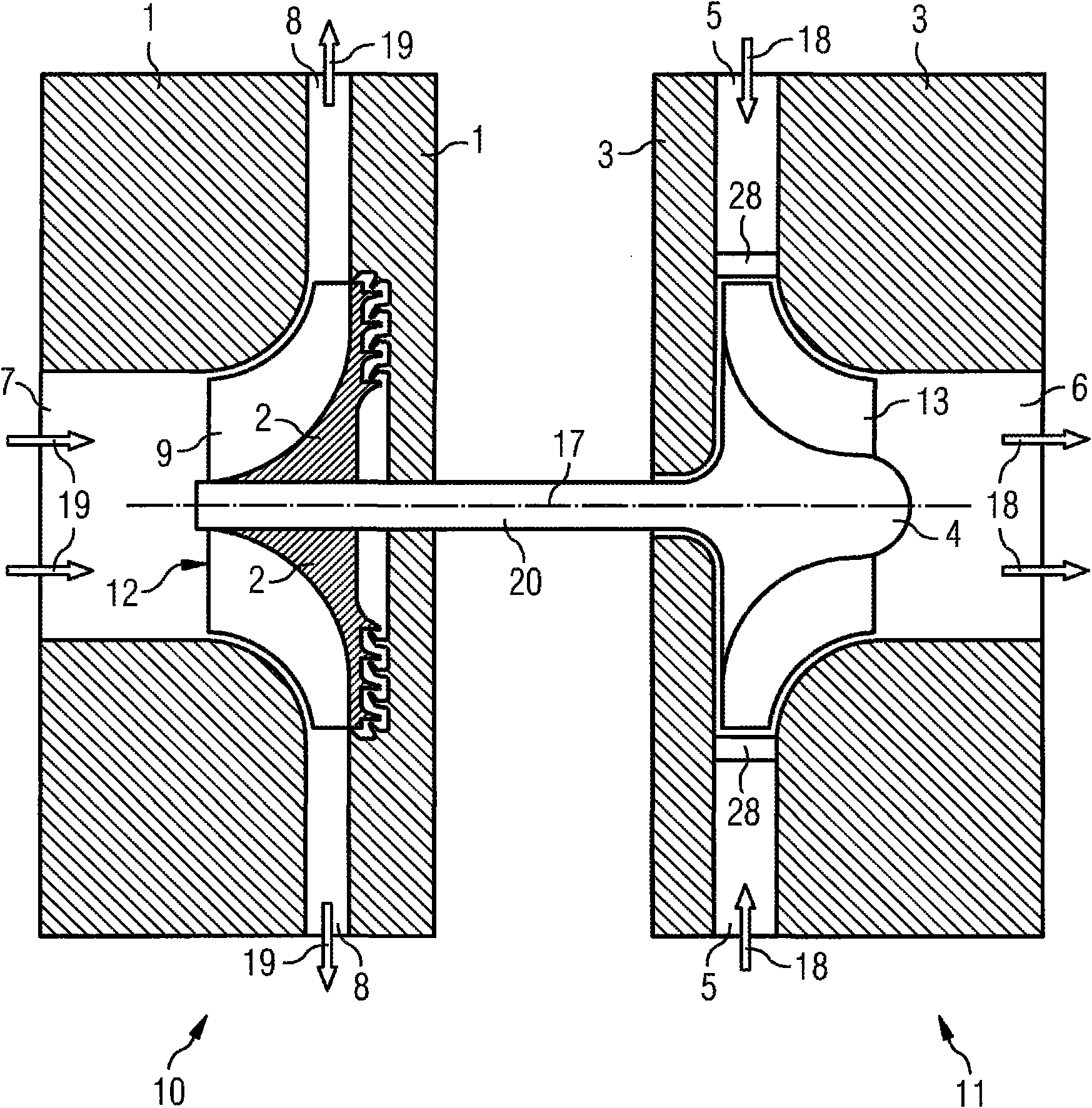
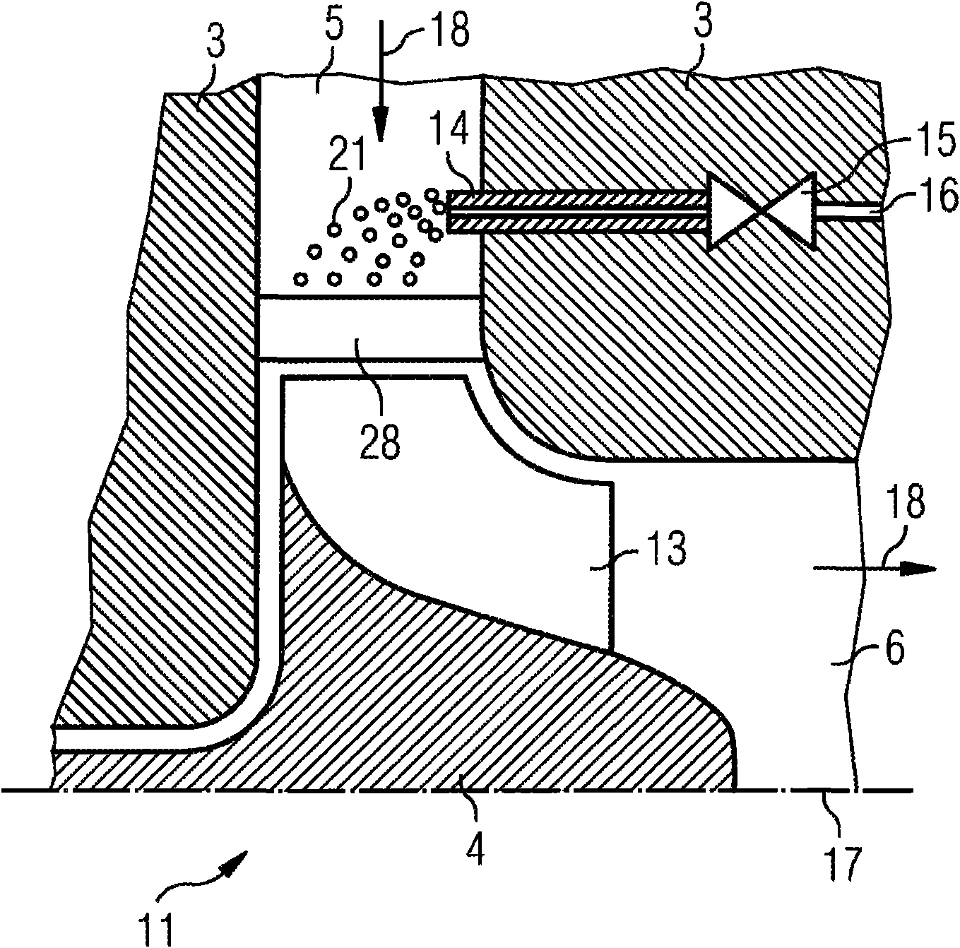
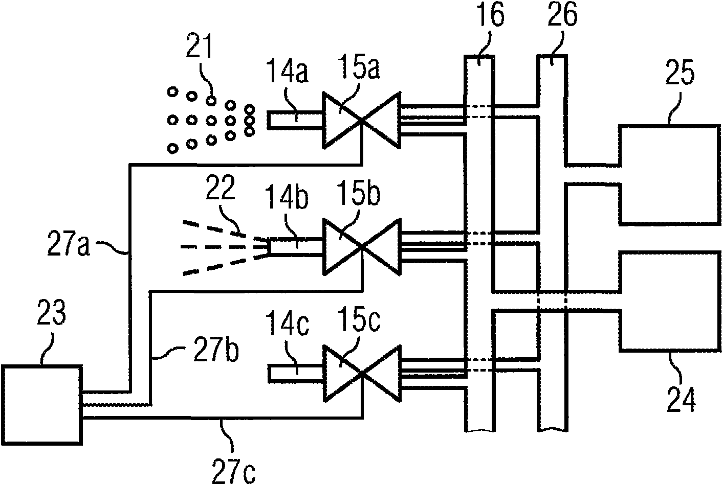
[0032] will now refer to Figure 1-3 Embodiments of the present invention will be described.

[0033] figure 1 A cross-sectional view of a turbocharger is schematically shown. The turbocharger includes a turbine 11 and a compressor 10 . The turbine 11 and the compressor 10 are connected by a shaft 20 .

[0034] The turbine 11 comprises a rotor 4 placed inside a turbine casing 3 . The turbine casing 3 has an exhaust gas inlet 5 to the rotor 4 such that exhaust gas entering the exhaust gas inlet 5 actuates the rotor 4 . Furthermore, the turbine housing 3 has an exhaust outlet 6 via which the exhaust gas from the rotor 4 leaves the turbine housing 3 . Arrow 18 indicates that the exhaust gas flow enters the turbine casing 3 through the exhaust inlet 5 , actuates the rotor 4 and then leaves the turbine casing 3 through the exhaust outlet 6 .

[0035] The compressor 10 includes an impeller 12 placed inside the compressor casing 1 . Furthermore, the compressor 10 has an air in...


PUM


Abstract

A method for cleaning a number of turbine blades (13, 28) of a turbine (11) under operation conditions by means of a cleaning fluid (21) which is sprayed onto the turbine blades (13, 28) by a number of nozzles (14) is disclosed. The method is characterised in that the cleaning fluid (21) is distributed to the nozzles (14) such that only a fraction of the nozzles (14) is used at any one time to spray the cleaning fluid (21) onto the turbine blades (13, 28). Furthermore, a turbine (11) comprising a number of rotor blades (13), a number of stator blades (28) and a number of nozzles (14) is described. Each nozzle (14) is connected to a cleaning fluid supply (24). The turbine (11) further comprises at least one distribution unit which is designed such that the cleaning fluid can be distributedto only a fraction of the nozzles (14) at any one time. Moreover, a turbocharger comprising an inventive turbine (11) is disclosed.

Description

technical field [0001] The invention relates to a method for cleaning turbine blades under operating conditions, a turbine and a turbocharger. Background technique [0002] Industrial diesel engines run on a variety of fuels, including heavy fuel oil. This lower grade of fuel has many impurities, which lead to the formation of ash and other compounds. Some ash and compounds are transported from the diesel engine exhaust manifold to the turbocharger turbine and can form thick, hard deposits on the turbine blades. This deposit leads to reduced turbocharger efficiency and increased engine combustion chamber temperatures. If this buildup grows in an unchecked manner, the engine power capacity will be reduced and damage to hot engine components will result. It can also cause damage to turbocharger components. [0003] In order to avoid deposit build-up, the turbocharger turbine is equipped with a cleaning device. Solid particles such as walnut shell chips or rice can be used...

Claims


Application Information

Patent Timeline
Patent Type & Authority Applications(China)
IPC IPC(8): F02B39/00F01D25/00F02C6/12F02B39/16F02B77/04
CPCF05D2270/44F05D2270/303F02B39/16F02C6/12F05D2220/40F01D25/002F05D2270/309F05D2270/64F05D2270/16F05D2270/304
Inventor 弗朗西斯·赫耶斯伊恩·平克尼
Owner NAPIER TURBOCHARGERS LTD
Learn More