
Feeding apparatus

A feeding device and feeding technology, applied in the direction of feeding device, positioning device, storage device, etc., can solve the problems of fast feeding speed, inability to bend, affect bending effect, etc., and achieve the effect of improving work efficiency

Inactive Publication Date: 2011-01-12
ZHANGJIAGANG MINGHUA MACHINERY MFG
View PDF9 Cites 6 Cited by
  • Summary
  • Abstract
  • Description
  • Claims
  • Application Information

AI Technical Summary

Problems solved by technology

In actual application, in some special occasions, the feeding speed cannot exceed 35mm / min, which is extremely slow. However, the above-mentioned feeding device has only one level of deceleration, which leads to too fast feeding speed, which affects the bending effect, and even cannot be bent.
In addition, the feeding speed of the current feeding device is the same as the retracting speed after bending, and the work efficiency is low

Method used


Image

  • Feeding apparatus
  • Feeding apparatus
  • Feeding apparatus

Examples


Embodiment Construction

[0016] Specific embodiments of the present invention will be described in detail below in conjunction with the accompanying drawings.

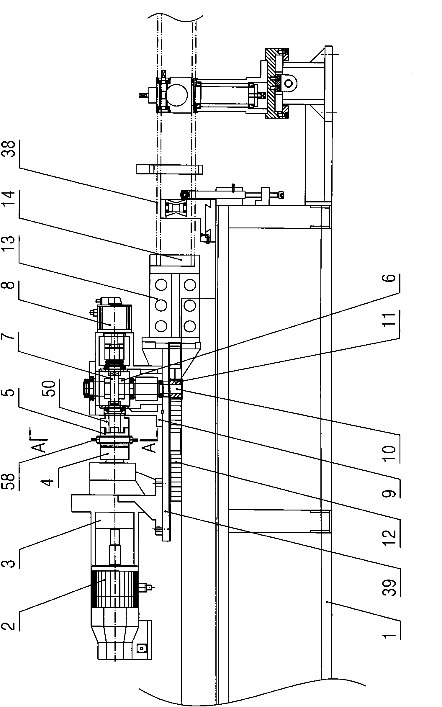
[0017] Such as figure 1 As shown, the feeding device of the present invention includes: a pair of parallel guide rails 40 arranged on the fuselage 1 and a feeding bottom plate 39 movably arranged on the pair of guide rails 40 through a slider 41—see Figure 5 As shown, the feeding bottom plate 39 is provided with a worm gear box 9, a feed motor 2 positioned at one side of the worm gear box 9, a feed reducer 3 and a reset motor 8 positioned at the other side of the worm gear box 9, and the output of the feed motor 2 The shaft is connected with the input shaft of the feed reducer 3, and the worm gear 6 is provided with the transmission shaft 10 in the vertical direction in the worm gear box 9. It meshes with the rack 12 arranged on the fuselage 1, and a horizontal worm 7 matched with the worm wheel 6 is also pierced in the worm gear box 9. A cl...


PUM


Abstract

The invention discloses a feeding apparatus capable of greatly reducing feeding speed, which comprises a main body, wherein the main body is movably provided with a feeding bottom plate; the feeding bottom plate is provided with a worm gear box, a feeding motor and a feeding reducer; the feeding motor and the feeding reducer are positioned at one side of the worm gear box; the output shaft of the feeding motor is connected with the input shaft of the feeding reducer; the transmission shaft according to the vertical direction in the worm box is provided with a worm gear; the bottom end of the transmission shaft extends out of the worm gear box and provided with a drive gear; the drive gear is meshed with a rack on the main body; a horizontal worm, which cooperates with the worm gear, penetrates through the worm gear box; one end of the worm is connected with the output shaft of the feeding reducer; and the feeding bottom plate is also provided with a feeding clamping device. The invention is mainly used for a hot bending machine capable of heating and then bending pipes.

Description

technical field [0001] The invention relates to a feeding device, in particular to a feeding device used on a pipe bending machine. Background technique [0002] At present, the structure of the feeding device on the pipe bending machine includes: a fuselage, a feeding base plate is movable on the body, a feeding motor and a feeding reducer are arranged on the feeding base plate, and the output shaft of the feeding motor is connected with the input shaft of the feeding reducer. , The output shaft of the feeding reducer is provided with a feeding clamping mold base, and the end of the feeding clamping mold base is provided with a clamping mold. In actual application, in some special occasions, the feeding speed cannot exceed 35mm / min, which is extremely slow. However, the above-mentioned feeding device has only one level of deceleration, which leads to too fast feeding speed, which affects the bending effect, and even cannot be bent. In addition, the feeding speed of the cur...

Claims


Application Information

Patent Timeline
Patent Type & Authority Applications(China)
IPC IPC(8): B21D43/02
Inventor 赵叶静王艳秋
Owner ZHANGJIAGANG MINGHUA MACHINERY MFG
Learn More