Squeezing machine

A squeezer and machine body technology, applied in the direction of presses, manufacturing tools, etc., can solve the problems of hand injury, high labor intensity, unreasonable structure, etc., and achieve the effect of improving safety factor, avoiding accidental injury, and improving labor productivity

Inactive Publication Date: 2011-01-12
JIANGSU HUALUN CHEM
View PDF5 Cites 7 Cited by
  • Summary
  • Abstract
  • Description
  • Claims
  • Application Information

AI Technical Summary

Problems solved by technology

[0002] Due to the unreasonable structure of the traditional press, the following defects are caused: 1. High material consumption and high cost; 2. Low safety factor. If the hand is not pulled out in time during the mold clamping process, it is easy to damage or even disable the hand; 3. Labor strong

Method used


Image

  • Squeezing machine
  • Squeezing machine
  • Squeezing machine

Examples


Embodiment Construction

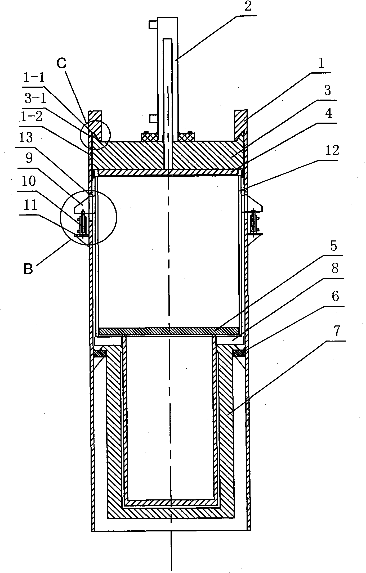
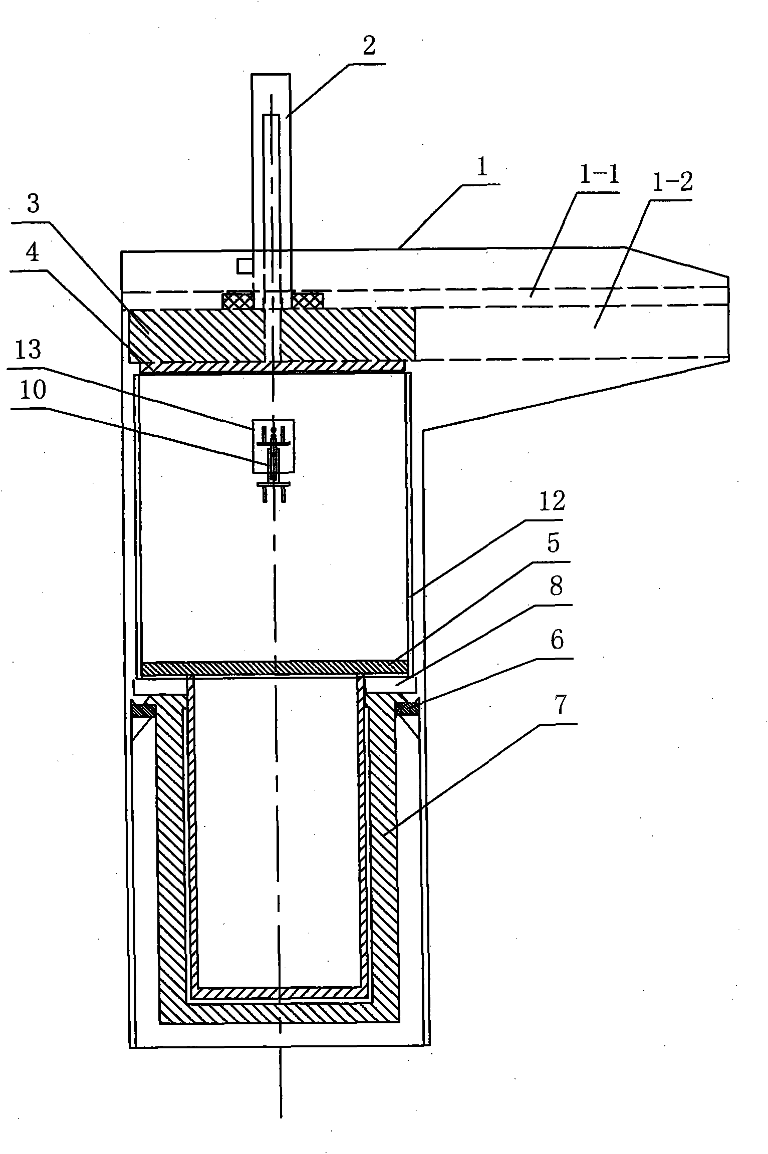
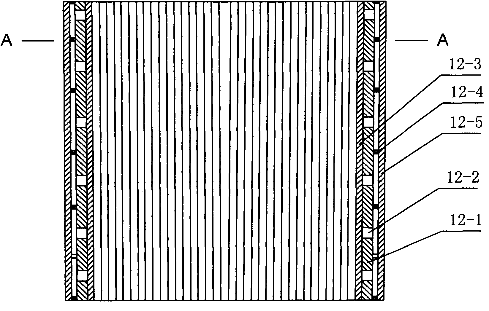
[0016] Such as figure 1 , 2 , shown in 5 and 6, is a kind of squeezing machine, comprises body 1, and radial groove 1-2 is arranged respectively on the left and right sides of the inner top of body 1, and a vertical through hole 13 is respectively arranged on the left and right sides of body 1, The body 1 is provided with a first oil cylinder 7 , a pressing die 12 and a top plate 3 .

[0017] The first oil cylinder 7 is fixed in the machine body 1 through the support plate 6 , the pressing die 12 is arranged above the first oil cylinder 7 , and the top plate 3 is arranged above the pressing die 12 . The left and right sides of the top plate 3 are respectively arranged in the radial grooves 1-2. The top of each radial groove 1-2 is respectively provided with a V-shaped groove 1-1, and the left and right sides of the top of the top plate 3 are respectively provided with protrusions 3-1 matching the V-shaped groove 1-1. The telescopic end of the first oil cylinder 7 is fixedly...


PUM


Abstract

The invention discloses a squeezing machine, relates to the field of structure of the squeezing machine for squeezing durene. The squeezing machine comprises a body, wherein the left side and the right side of the top in the body are provided with radial grooves respectively; the left side and the right side of the body are provided with vertical through holes respectively; a first oil cylinder, a squeezing mould and a top plate are arranged in the body; the first oil cylinder is fixed in the body through a supporting plate; the squeezing mould is arranged above the first oil cylinder; the top plate is arranged above the squeezing mould; the left side and the right side of the top plate are arranged in the radial grooves respectively; a telescopic end of the first oil cylinder is fixedly connected with a working plate; the working plate is arranged in the squeezing mould; an oil collection groove is formed between the squeezing mould and the first oil cylinder; the outer side of the squeezing mould is fixedly connected with more than two upper connecting plates; each upper connecting plate is inserted into the corresponding vertical through hole and connected with a piston rod of the second oil cylinder respectively; and the lower end of each second oil cylinder is fixed on the outer side of the body through the lower connecting plate. The squeezing machine has the advantages of greatly improving the labor productivity, along with high safety.

Description

technical field [0001] The invention relates to a mechanical solid-liquid separation device, in particular to the structural field of a pressing machine. Background technique [0002] Due to the unreasonable structure of the traditional press, the following defects are caused: 1. High material consumption and high cost; 2. Low safety factor. If the hand is not pulled out in time during the mold clamping process, it is easy to damage or even disable the hand; 3. Labor Strong. Contents of the invention [0003] The purpose of the present invention is to overcome the deficiencies of the prior art and provide a safe and high-efficiency press. [0004] The object of the present invention is achieved in this way: a press machine, including a machine body, radial grooves are respectively arranged on the left and right sides of the top inside the body, a vertical through hole is respectively arranged on the left and right sides of the body, and the first An oil cylinder, a press...

Claims


Application Information

Patent Timeline
Patent Type & Authority Applications(China)
IPC IPC(8): B30B9/02B30B15/02B30B15/28
Inventor 陈忠平张竹来
Owner JIANGSU HUALUN CHEM
Why Eureka
Try Eureka