Pneumatic sealing control device at discharge port of screw conveyor

An auger conveyor and control device technology, which is applied to the conveyor control device, conveyor objects, transportation and packaging, etc., can solve the problems of material waste, heavy cleaning and cleaning workload, and uncompact equipment, to prevent Waste and environmental pollution problems, ensuring packaging measurement accuracy, ensuring the effect of weighing accuracy

Inactive Publication Date: 2011-01-12
颜旺洪 +1
View PDF0 Cites 4 Cited by
  • Summary
  • Abstract
  • Description
  • Claims
  • Application Information

AI Technical Summary

Problems solved by technology

[0002] Quantitative packaging scales and batching scales must use auger conveyors to feed materials when weighing and packaging powdery and fine granular materials. When the scale is full and stop feeding, materials will still flow from the blades of the fast and slow auger conveyors. It flows out automatically and enters the weighing hopper or weighing bag, seriously affecting the weighing accuracy; when filling powder with low water content and good fluidity, such as starch and premixed feed containing stone powder, clay, bone meal and its mineral elements , when the fast and slow auger conveyor is not working, the material will flow into the weighing bucket or weighing bag by itself. Like mudslides rushing to every corner of the workshop, it will not only cause waste of materials, but also cause flying dust, which seriously pollutes the environment of the production site. The workload of cleaning and cleaning is heavy, and the labor intensity is relatively high.
In order to prevent the self-flow of materials in the packaging scale, people increase the length of the auger conveyor, or reduce the pitch of the auger, or make the auger conveyor an inclined auger with an outlet higher than the import, or take the former into consideration. , although these improvement schemes will improve the self-flow of materials, they cannot be completely cured. The implementation of these schemes not only increases the cost, but also increases the length of the auger conveyor. The whole equipment is not compact and occupies a large area. Therefore, it cannot be popularized and applied in actual production

Method used


Image

  • Pneumatic sealing control device at discharge port of screw conveyor
  • Pneumatic sealing control device at discharge port of screw conveyor
  • Pneumatic sealing control device at discharge port of screw conveyor

Examples


specific Embodiment approach

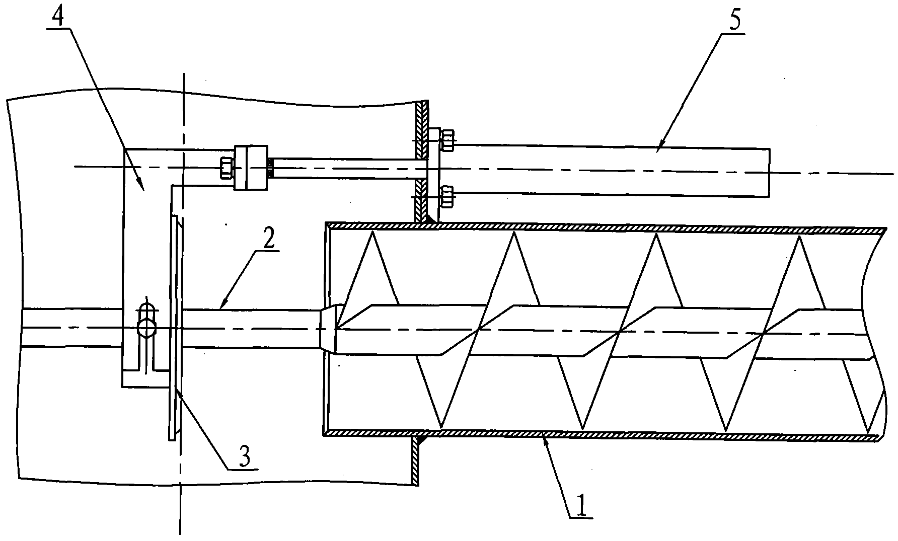
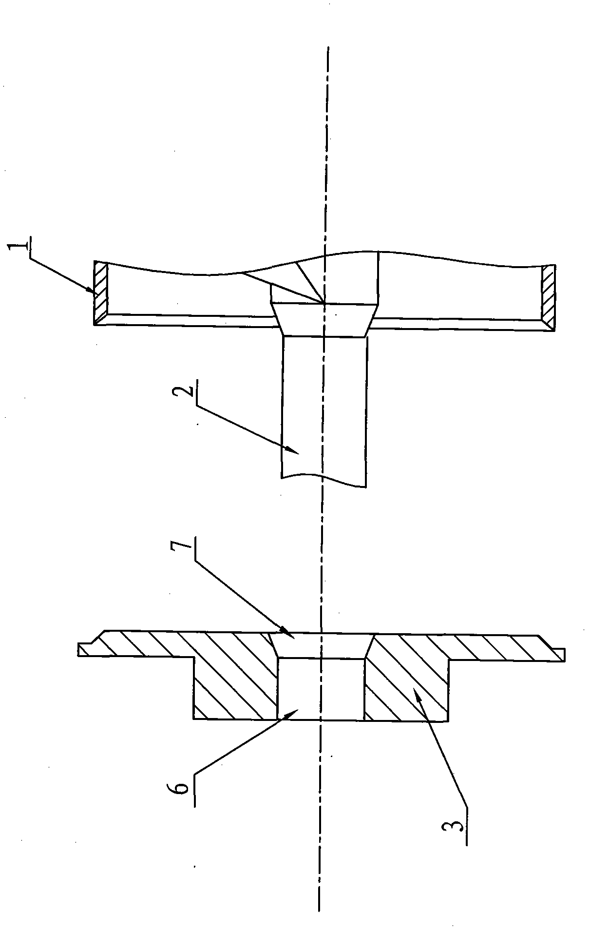
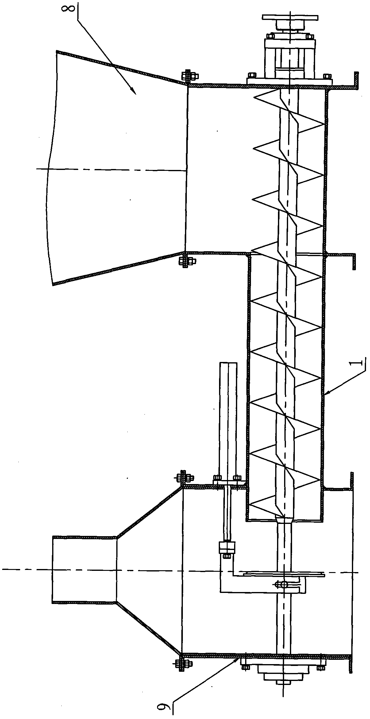
[0014] attached Figure 1 ~ Figure 3 It is a schematic diagram of the structure arranged between the feed hopper 8 and the discharge hopper 9 in the present invention, the pneumatic sealing control device of the discharge port of the auger conveyor includes the auger conveying pipe 1, the auger shaft 2, the plugging Cover 3, connecting seat 4 and cylinder 5, the plugging cover 3 is fixed on the connecting seat 4, the cylinder 5 is a two-rod cylinder, the connecting seat 4 is fixedly connected with two synchronous piston rods of the cylinder 5, and the plugging cover 3 A shaft hole 6 is provided in the center of the shaft hole 6, and an axial sealing surface 7 is provided on the outside of the shaft hole 6. The axial sealing surface 7 is a tapered sealing surface. The plugging cover 3 is set on the auger shaft 2 through the shaft hole 6. The plugging cover 3 is controlled by the cylinder 5. When the auger conveyor is in the state of stopping discharging, the cylinder 5 is in th...


PUM


Abstract

The invention relates to a pneumatic sealing control device at the discharge port of a screw conveyor, which comprises an screw delivery pipe, a screw shaft, a plugging cover, a connecting base and a cylinder, wherein the plugging cover is fixed on the connecting base, the connecting base is fixedly connected with a piston rod of the cylinder, the center of the plugging cover is provided with an axle hole, the outer side of the axle hole is provided with an axial sealing surface, the plugging cover is sheathed on the screw shaft, and the plugging cover is controlled by the cylinder. In the state of stopping discharge, the space between the plugging cover and the end surface of the screw delivery pipe, and the space between the inner hole of the plugging cover and the screw shaft are both in a sealing and plugging state; and in the state of keeping discharge, the plugging cover is away from the outlet end surface of the screw delivery pipe. The pneumatic sealing control device can duly plug the discharge port according to the conveying process requirements and effectively solve the problem of automatic flow of materials in case of stopping the feed, thereby ensuring the packing and measuring accuracy of the packing scale, preventing the waste and the environmental pollution caused by outflow of the materials and improving the working environment of workers.

Description

technical field [0001] The invention relates to the field of packaging and batching machinery, in particular to an auger feeder used in conjunction with quantitative packaging scales and batching scales. Background technique [0002] Quantitative packaging scales and batching scales must use auger conveyors to feed materials when weighing and packaging powdery and fine granular materials. When the scale is full and stop feeding, materials will still flow from the blades of the fast and slow auger conveyors. It flows out automatically and enters the weighing hopper or weighing bag, seriously affecting the weighing accuracy; when filling powder with low water content and good fluidity, such as starch and premixed feed containing stone powder, clay, bone meal and its mineral elements , when the fast and slow auger conveyor is not working, the material will flow into the weighing bucket or weighing bag by itself. Like mudslides rushing to every corner of the workshop, it will n...

Claims


Application Information

Patent Timeline
Patent Type & Authority Applications(China)
IPC IPC(8): B65G43/08
Inventor 颜旺洪颜旺东
Owner 颜旺洪
Why Eureka
Try Eureka