Collecting pipe structure for heat exchanger

A technology for heat exchangers and headers, applied in the field of header structures, can solve problems such as the inability to further improve the heat exchange efficiency of the heat exchanger, achieve good positioning consistency, improve heat exchange efficiency, and reduce eroded products the possible effect of

Active Publication Date: 2011-01-12
浙江新金宸机械有限公司
View PDF8 Cites 27 Cited by
  • Summary
  • Abstract
  • Description
  • Claims
  • Application Information

AI Technical Summary

Problems solved by technology

However, it is difficult to evenly distribute the medium to flow through each flat tube for heat exchange without designing a uniform structure of the header, and it is impossible to further improve the heat exchange efficiency of the heat exchanger.

Method used


Image

  • Collecting pipe structure for heat exchanger
  • Collecting pipe structure for heat exchanger
  • Collecting pipe structure for heat exchanger

Examples


Embodiment

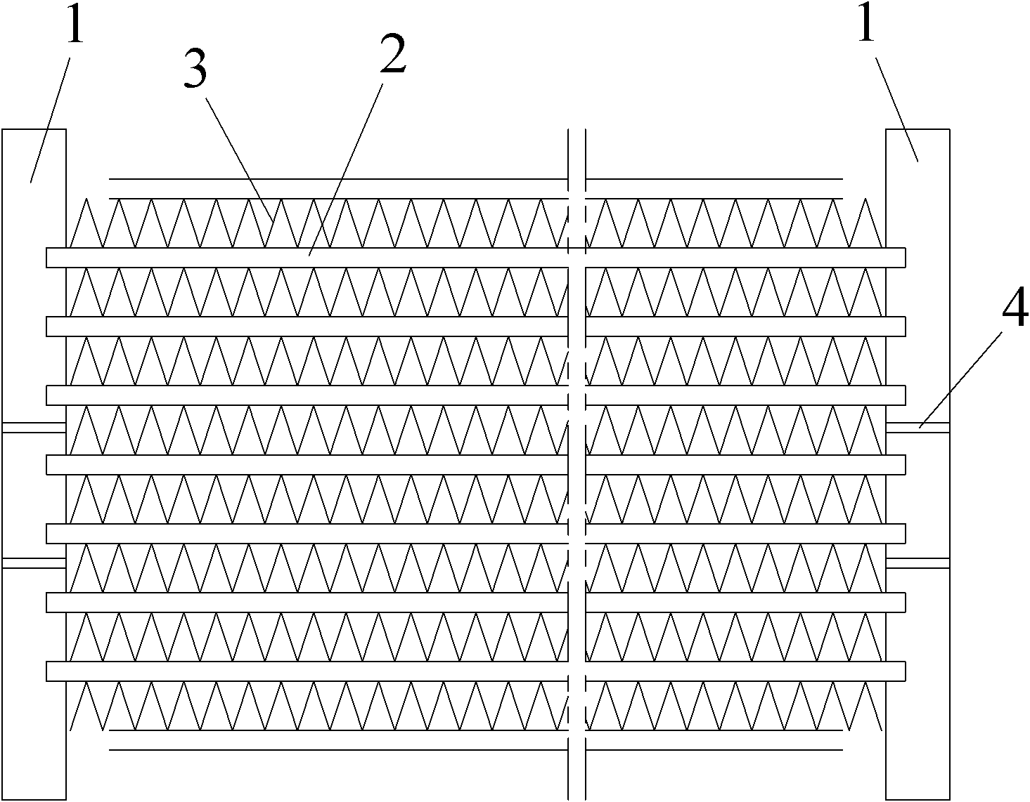
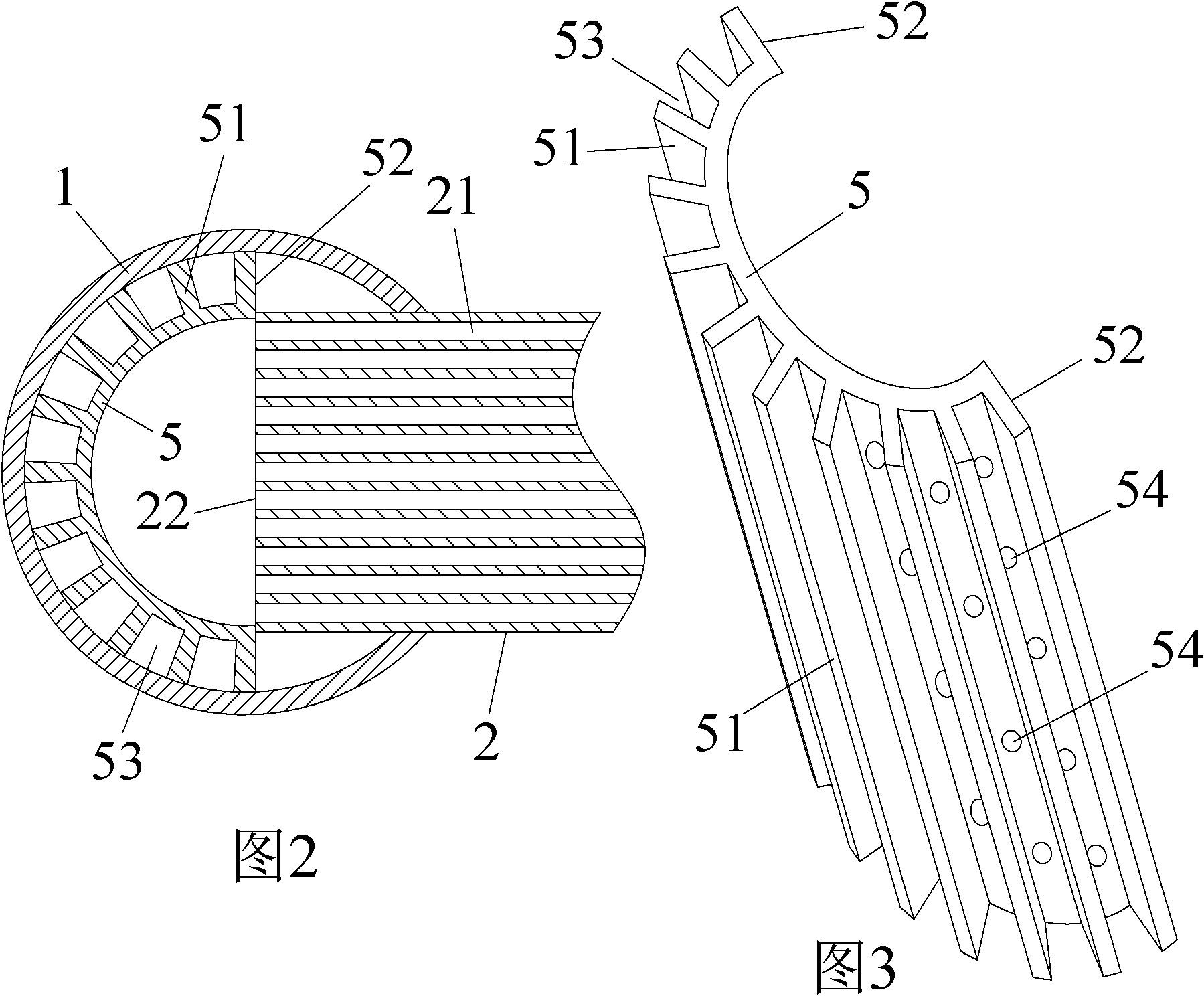
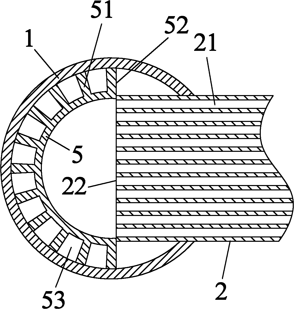
[0012] Example: see figure 1 and figure 2 , the present invention is provided with an interface for inserting the heat dissipation flat tube on one side of the collector, the heat dissipation flat tube is plugged into the collector through the interface, and fins 3 are provided between adjacent flat tubes 2, and the heat dissipation flat tube The microchannel connects the two left and right headers, and there is also a separator 4 in the header 1, which divides the cavity of the header into several small chambers, which is conducive to evenly distributing the medium and improving the heat exchange efficiency of the flat tube . see figure 2 , the inner cavity of the header 1 is provided with a positioning lining 5 on the opposite side of the interface, the inner end surface 22 of the heat dissipation flat tube 2 is set against the positioning surface 52 of the positioning lining 5, and the positioning lining 5 There are several ribs 51 on the outer side, and the positionin...


PUM


Abstract

The invention discloses a collecting pipe structure for a heat exchanger. A positioning liner is arranged on an opposite side of an interface in an inner cavity of a collecting pipe; an inner end face of a radiating flat pipe is pressed against a positioning surface of the positioning liner; a plurality of ribs are arranged outside the positioning liner; the positioning liner is brazed and fixed on an inner surface of the collecting pipe through the external side faces of the ribs; the space between adjacent ribs forms a medium distribution microchannel; a plurality of medium distribution through holes are formed on the side wall of the positioning liner and are communicated with the medium distribution microchannel; and the number of the medium distribution through holes is reasonably designed so as to uniformly distribute the medium to flow through each flat pipe. The collecting pipe structure for the heat exchanger has the advantages of high positioning consistency of the flat pipe, contribution to uniformly distributing the medium to flow through each flat pipe, achieving the radiating effect of all flat pipes, improving the heat exchange efficiency of the heat exchanger, reducing the possibility that redundant melted solder corrodes products, and contributing to prolonging the service life of the products.

Description

technical field [0001] The invention relates to a component of a heat exchanger, in particular to a header structure of the heat exchanger. Background technique [0002] A heat exchanger is a device that realizes heat transfer between hot and cold fluids, and is widely used in HVAC and other fields. The heat exchanger generally includes two collectors parallel to each other, a number of substantially parallel heat dissipation flat tubes are arranged between the two collectors, and fins for heat dissipation are brazed between adjacent flat tubes. In the prior art, the positioning liner is often installed in the cavity of the collecting pipe. When assembling the flat pipe, the flat pipe can be neatly assembled into the collecting pipe. After brazing, the positioning lining is fixed on the inner wall of the collecting pipe. , which greatly simplifies the assembly process. Such a positioning inner liner is integrally brazed and fixed on the inner wall of the collector, and the...

Claims


Application Information

Patent Timeline
Patent Type & Authority Applications(China)
IPC IPC(8): F28F9/02
Inventor 何金汉
Owner 浙江新金宸机械有限公司
Why Eureka
Try Eureka