
Touch screen and electronic device therewith

A technology of electronic devices and touch screens, applied to the conductive layer on the insulating carrier, the structure of the telephone, and the processing of electrical digital data, etc., can solve the problem that the frame cannot be further reduced, achieve the effect of reducing the width and improving the reliability

Active Publication Date: 2011-01-12
INNOCOM TECH (SHENZHEN) CO LTD +1
View PDF3 Cites 21 Cited by
  • Summary
  • Abstract
  • Description
  • Claims
  • Application Information

AI Technical Summary

Problems solved by technology

[0009] In order to solve the problem that the frame of the touch screen in the prior art cannot be further reduced, the present invention provides a touch screen with a narrower frame

Method used


Image

  • Touch screen and electronic device therewith
  • Touch screen and electronic device therewith
  • Touch screen and electronic device therewith

Examples


Embodiment Construction

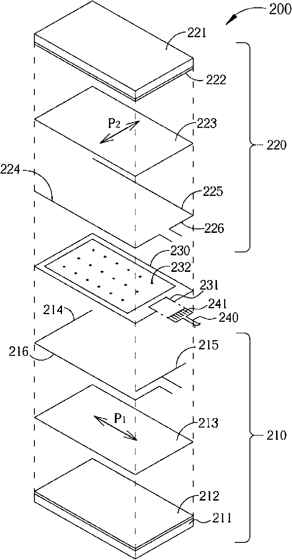
[0027] figure 2 It is a combination diagram of a preferred embodiment of the resistive touch screen of the present invention. The touch screen 200 is formed by stacking two conductive films 210, 220, and the two conductive films 210, 220 are bonded and fixed with an annular colloid layer 230, and a plurality of insulating spacers 232 (spacers) are evenly distributed in the center, so that the two conductive films 210, 220 maintain a fixed distance.

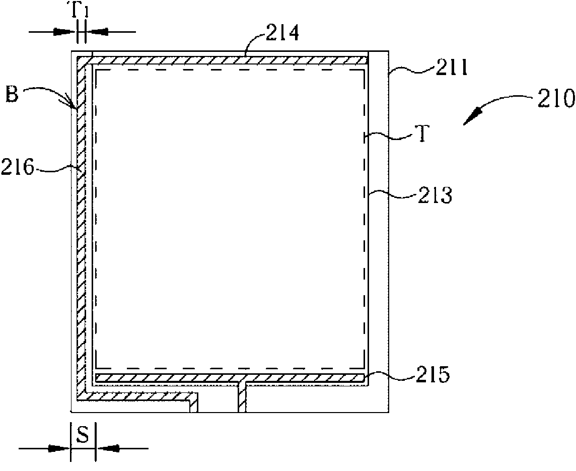
[0028] The conductive film 210 includes a substrate 211 , and a conductive layer 213 is bonded and fixed on the surface of the substrate 211 through the colloid layer 212 . An electrode 214 , an electrode 215 and peripheral wires 216 are further disposed on the surface of the conductor layer 213 . Wherein the electrodes 214 , 215 are arranged parallel to each other on opposite side edges of the conductive layer 213 . The peripheral wire 216 is an extension of the electrode 214 , which extends in parallel along the outer edge o...


PUM


Abstract

The invention relates to a touch screen applied to an electronic device, comprising a first base board and a second base board with are overlapped with each other, wherein the first base board is provided with a first conducting layer and a first peripheral conducting wire; and the second base board is provided with a second conducting layer arranged at one side opposite to the first conducting layer. The surface resistances of the first conducting layer and the second conducting layer are 1k omega / -800k omega / , the first base board and the second base board are divided into a touch area and an edge area from the overlapping area of the first conducting layer and the second conducting layer, the first peripheral conducting wire passes through the edge area, and the width of the edge area is 100 mu m-1 mm.

Description

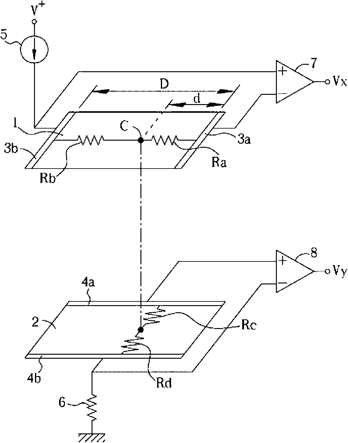
technical field [0001] The invention relates to a touch screen structure, in particular to a resistive touch screen using a carbon nanotube conductive layer, and an electronic device using the touch screen. Background technique [0002] US Pat. No. 4,672,153 and US Pat. No. 4,897,511 respectively disclose a resistive touch screen structure and a position sensing method. Such as figure 1 As shown, the four-wire resistive touch screen in the prior art includes two first conductive films 1 and second conductive films 2 stacked on each other. The surfaces of the first conductive film 1 and the second conductive film 2 are formed of transparent conductive materials. The conductive layer has two parallel X-axis electrodes 3a, 3b on the left and right sides of the first conductive film 1, and two parallel Y-axis electrodes 4a, 4b on the upper and lower sides of the second conductive film 2. The X-axis electrode 3b is electrically connected to a current source 5, so that the first...

Claims


Application Information

Patent Timeline
Patent Type & Authority Applications(China)
IPC IPC(8): G06F3/041G06F3/045G06F1/16H04M1/02
CPCG06F3/045G06F2203/04103H01B5/14
Inventor 郑嘉雄吴志笙胡君怡赵志涵
Owner INNOCOM TECH (SHENZHEN) CO LTD
Learn More