Residual heat recovery system and operation method thereof

A waste heat recovery system and electronically controlled valve technology, which can be used in heating devices and other non-combustion heat generation directions, can solve the problems of waste and difficulty in recycling, and achieve the effect of large waste heat recovery efficiency.

Inactive Publication Date: 2011-01-19
CHINA FIRST HEAVY IND +1
View PDF6 Cites 3 Cited by
  • Summary
  • Abstract
  • Description
  • Claims
  • Application Information

AI Technical Summary

Problems solved by technology

The waste heat of solid materials with residual temperature, such as high-temperature sintered materials, coke, steel, castings, heat treatment parts, etc., is difficult to recover due to the intermittent and scattered nature of the discharge, and there is no effective technology to recover this part of waste heat use to cause waste

Method used


Image

  • Residual heat recovery system and operation method thereof
  • Residual heat recovery system and operation method thereof

Examples


Embodiment Construction

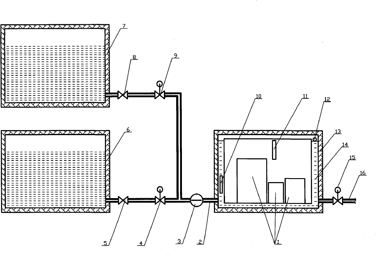
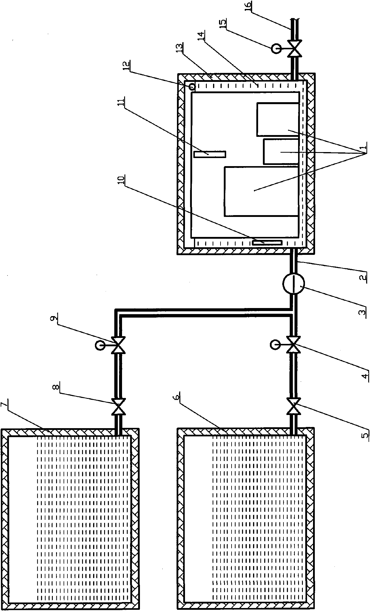
[0016] The present invention will be further described below in conjunction with the accompanying drawings. Such as figure 1 As shown, a waste heat recovery system includes an electronically controlled water pump 3, a boiling water incubator 6, a warm water incubator 7, a temperature sensor A10, a temperature sensor B11, a liquid level sensor 12, an incubator 13 and a cooling water tank 14. The heat preservation Cooling water tank 14 is installed in the case 13, and left and right sides respectively have a pipeline interface, and the interface on the left is connected with boiling water incubator 6 by pipeline A2, electric control water pump 3, electric control valve A4, one-way valve A5, and At the same time, the pipeline A2, the electric control water pump 3, the electric control valve B9, the one-way valve B8 are connected with the warm water incubator 7, and the interface on the right is connected to the pipeline B16, and the pipeline B16 is equipped with an electric contr...


PUM


Abstract

The invention discloses a residual heat recovery system and an operation method thereof. The system comprises an electrically controlled water pump, a boiling water insulation can, a warm water insulation can, a temperature sensor A, a temperature sensor B, a liquid level sensor, a insulation can and a cooling water tank, wherein the insulation tank is internally provided with the cooling water tank, the left side and the right side of the insulation tank are respectively provided with a pipeline connector, the left connector is connected with the boiling water insulation can through a pipeline A, the electrically controlled water pump, an electrically controlled valve A and a one-way valve A and is connected with the warm water insulation can through the pipeline A, the electrically controlled water pump, an electrically controlled valve B and a one-way valve B, the right connector is connected with a pipeline B, and the pipeline B is provided with an electrically controlled valve C. The method comprises a boiling water recovery step and a warm water recovery step. As the structure in which the insulation can is lined with the cooling water tank is adopted, heat transfer can only be carried out between the high-temperature objects in the cooling water tank and the cooling water in the cooling water tank, so that the high-temperature heat energy can be transformed to the boiling water and the warm water, as a result, the purpose of recovering residual heat is achieved, and the residual heat recovery efficiency can reach more than 80%.

Description

technical field [0001] The invention relates to a solid-phase waste heat recovery and utilization technology for industries with solid waste heat discharge, such as iron and steel plants, foundries, heat treatment plants, coking plants, and cement plants, in particular to a waste heat recovery system and its working method. Background technique [0002] At present, waste heat recovery and utilization technologies in industries such as iron and steel plants, foundries, heat treatment plants, coking plants, and cement plants are mainly focused on the waste heat recovery of high-temperature flue gas. Because of the continuous discharge, waste heat is easy to recover. Recycling to generate electricity. The waste heat of solid materials with residual temperature, such as high-temperature sintered materials, coke, steel, castings, heat treatment parts, etc., is difficult to recover due to the intermittent and scattered nature of the discharge, and there is no effective technology ...

Claims


Application Information

Patent Timeline
Patent Type & Authority Applications(China)
IPC IPC(8): F24J3/00
Inventor 陈佑钢刘宁宋清玉王宪周张福录
Owner CHINA FIRST HEAVY IND
Why Eureka
Try Eureka