Programmable electronic load

An electronic load and program-controlled technology, which is applied in the direction of measuring electricity, measuring electrical variables, and components of electrical measuring instruments, etc., can solve the problem of single dynamic load form, poor adjustment and control adaptability and real-time performance, and inability to adjust and control loads in real time Current and other problems, to achieve the effect of improving the dynamic test speed and the amplitude

Inactive Publication Date: 2011-01-19
东莞市锐源仪器股份有限公司
View PDF4 Cites 10 Cited by
  • Summary
  • Abstract
  • Description
  • Claims
  • Application Information

AI Technical Summary

Problems solved by technology

Currently widely used programmable electronic loads are used to adjust and control the load current by using hardware analog circuits. The adaptability and real-time performance of adjustment and control are poor, and they cannot adapt to the specific conditions of different power supplies, and cannot adjust and control loads in real time. electric current
The general programmable electronic load only has the function of static load, and the electronic load instrument with dynamic load function can only realize dynamic switching between two different load positions. The form of dynamic load is single, which cannot meet some higher requirements and special tests. needs

Method used


Image

  • Programmable electronic load
  • Programmable electronic load
  • Programmable electronic load

Examples


Embodiment Construction

[0009] The main idea of ​​the present invention is to overcome the shortcomings of the prior art and provide a programmable electronic load, which is superimposed by two current signals, and then amplified by the signal and measured by AD, which improves the dynamic test speed. The following detailed description will be given in conjunction with the embodiments with reference to the accompanying drawings in order to give a more in-depth interpretation of the technical features and advantages of the present invention.

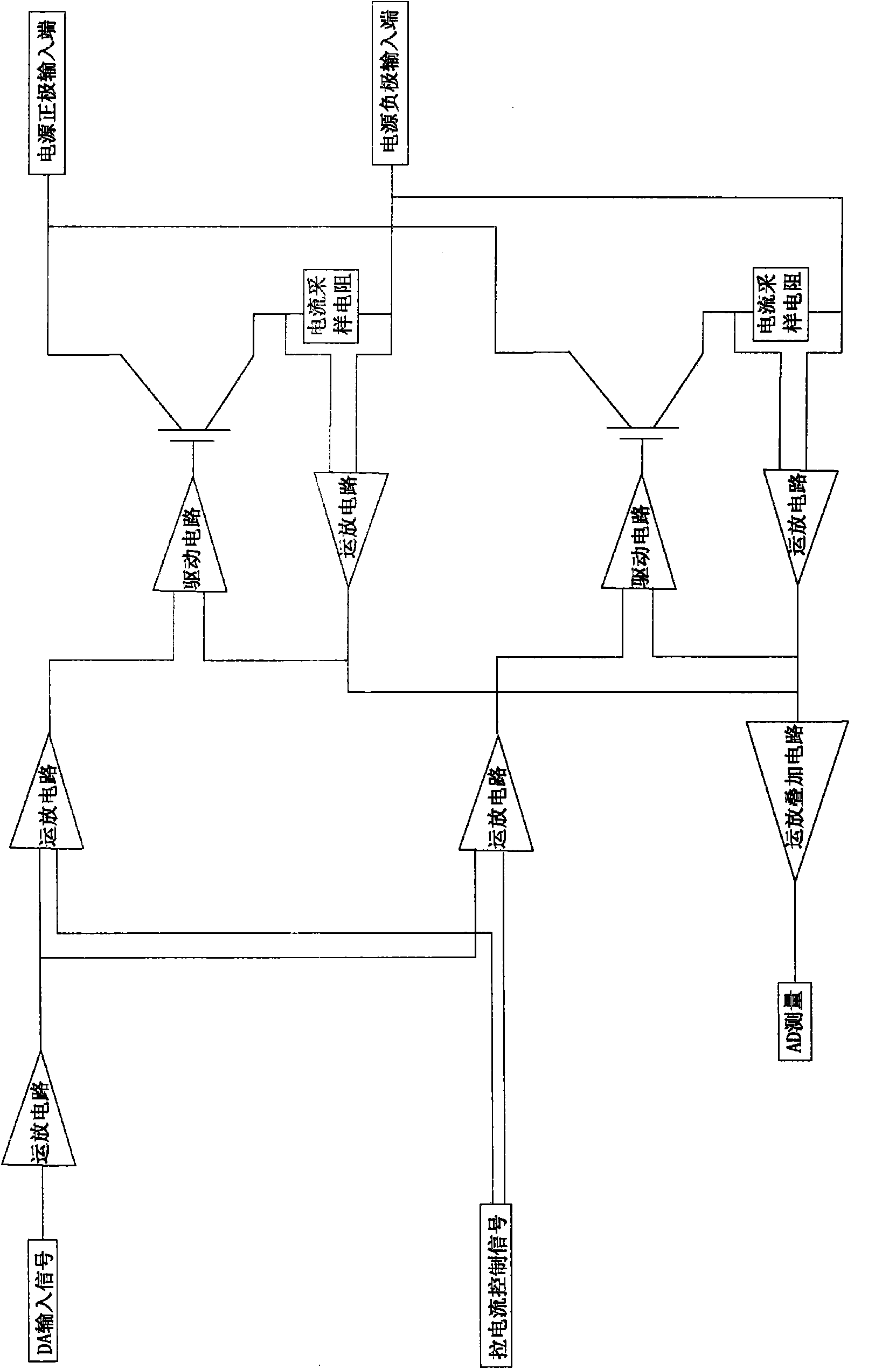
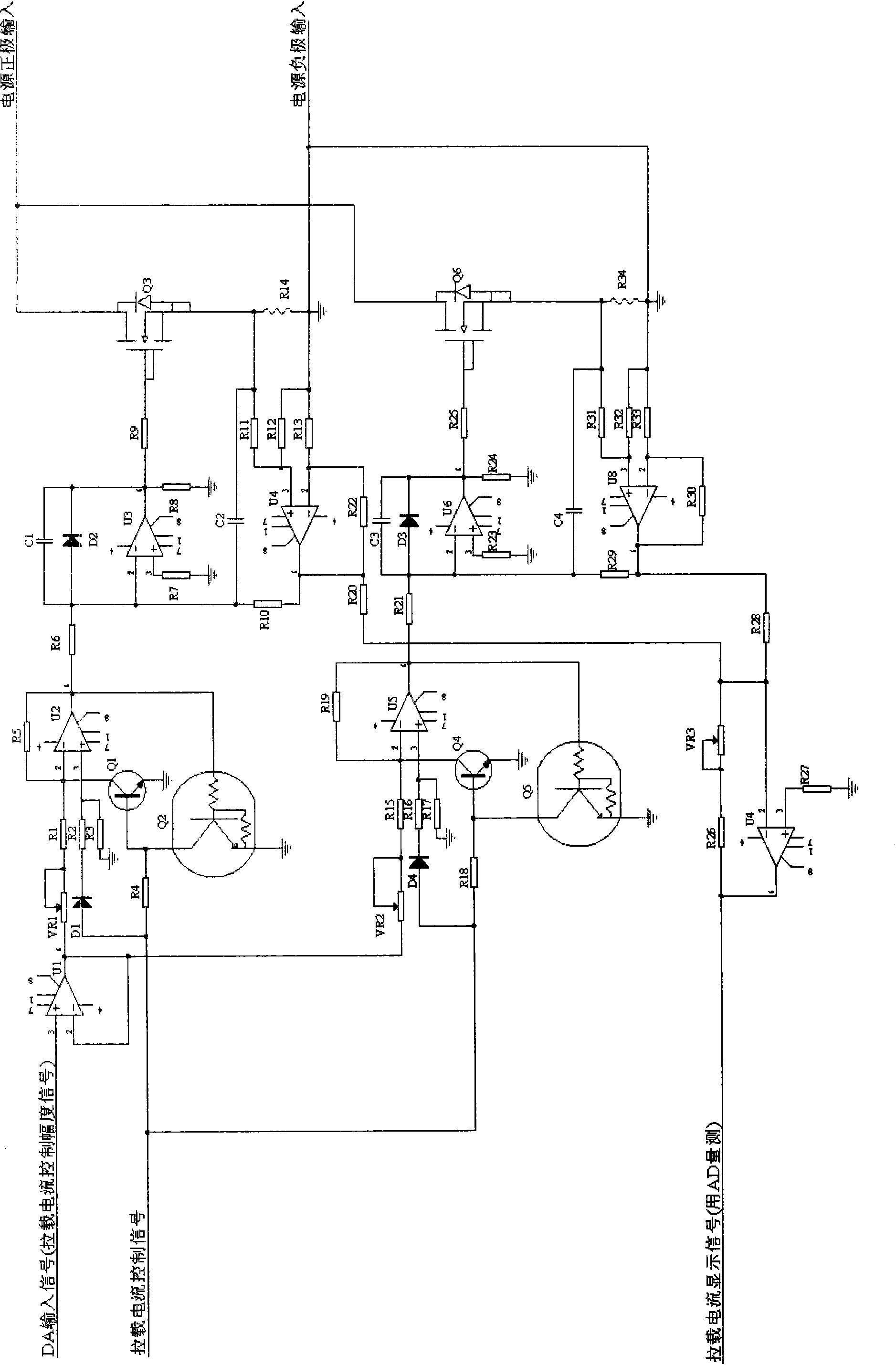
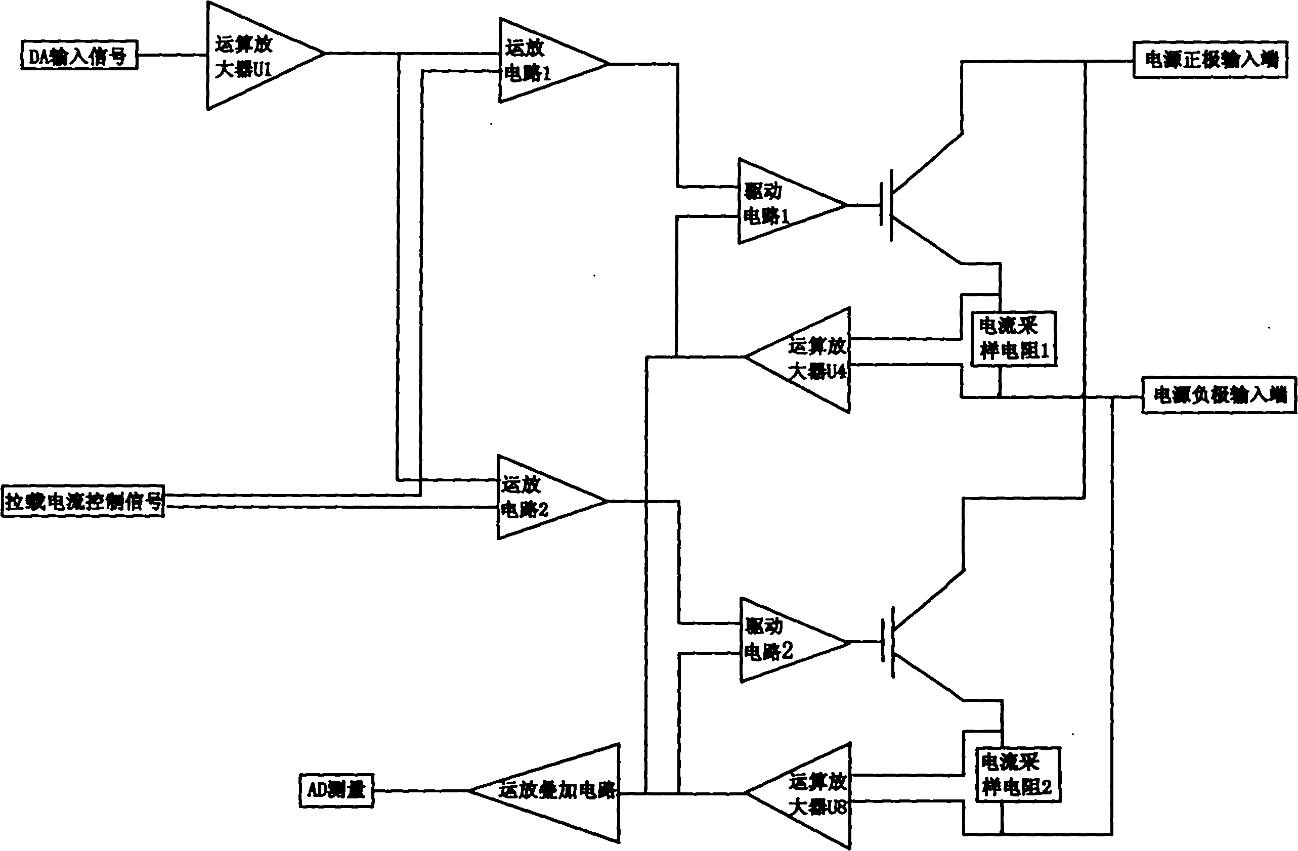
[0010] The principle block diagram of the present invention is as figure 1 As shown, a programmable electronic load is superimposed by two current signals, and then the amplified signal is measured by AD. The two circuits have the same structure, and the circuit is composed of an operational amplifier circuit, a driving circuit, a field effect tube, and an operational amplifier superimposing circuit.

[0011] The DA signal is amplified once and the load current contr...


PUM


Abstract

The invention discloses a programmable electronic load. The electronic load is measured by AD after amplifying two paths of current signals by superposition. The two paths of circuits have the same structure and consist of an operational amplifier circuit, a drive circuit, a field effect transistor and an operational amplifier superposition circuit which are connected in turn respectively. A DA signal is amplified once, connected with an input end of the operational amplifier circuit with a tensile load current control signal, amplified and then output to a drive amplifying circuit; the signal is output by the drive amplifying circuit and then connected with a gate of the field effect transistor; a source of the field effect transistor is connected with a positive electrode of a power supply, while a drain is connected with a negative electrode of the power supply through current sampling resistors which are connected in series; the two ends of the current sampling resistors are connected with an in-phase input end and an inverting input end of an operational amplifier respectively; and one path of the signal is connected with the drive amplifying circuit after being output by the operational amplifier, and the other path of signal is superposed with another circuit to be amplified to perform AD measurement. By adopting superposition of two paths of current signals, dynamic test of the signal from a high end to a low end can be realized, output of any dynamic load current waveform is realized, and dynamic test speed is improved.

Description

Technical field [0001] The invention relates to an electronic load, in particular to a programmable electronic load applying dynamic testing. Background technique: [0002] The function of the programmable electronic load is to adjust and control the load current to simulate various load waveform characteristics. At present, the widely used programmable electronic load adjusts and controls the load current by the method of hardware analog circuit. The adjustment and control have poor adaptability and real-time performance, and cannot adapt to the specific conditions of different power supplies, and cannot adjust and control the load in real time. Current. The general programmable electronic load only has the function of static load, and the electronic load meter with dynamic load function only realizes dynamic switching between two different load positions. The dynamic load has a single form and cannot meet some higher requirements and special tests. Needs. Summary of the inve...

Claims


Application Information

Patent Timeline
Patent Type & Authority Applications(China)
IPC IPC(8): G01R1/28
Inventor 吴锦来
Owner 东莞市锐源仪器股份有限公司
Why Eureka
Try Eureka