Backboard, board card and network device

A technology for backplanes and boards, which is applied in the field of boards and network equipment and backplanes, can solve problems such as heat loss and interference, and achieve the effect of reducing interference

Active Publication Date: 2011-01-19
BEIJING XINWANG RUIJIE NETWORK TECH CO LTD
View PDF2 Cites 8 Cited by
  • Summary
  • Abstract
  • Description
  • Claims
  • Application Information

AI Technical Summary

Problems solved by technology

[0008] The present invention provides a backplane, board and network equipment, which are used to solve the problem of heat loss and interference caused by high current when transmitting large current in the prior art

Method used


Image

  • Backboard, board card and network device
  • Backboard, board card and network device
  • Backboard, board card and network device

Examples


Embodiment 1

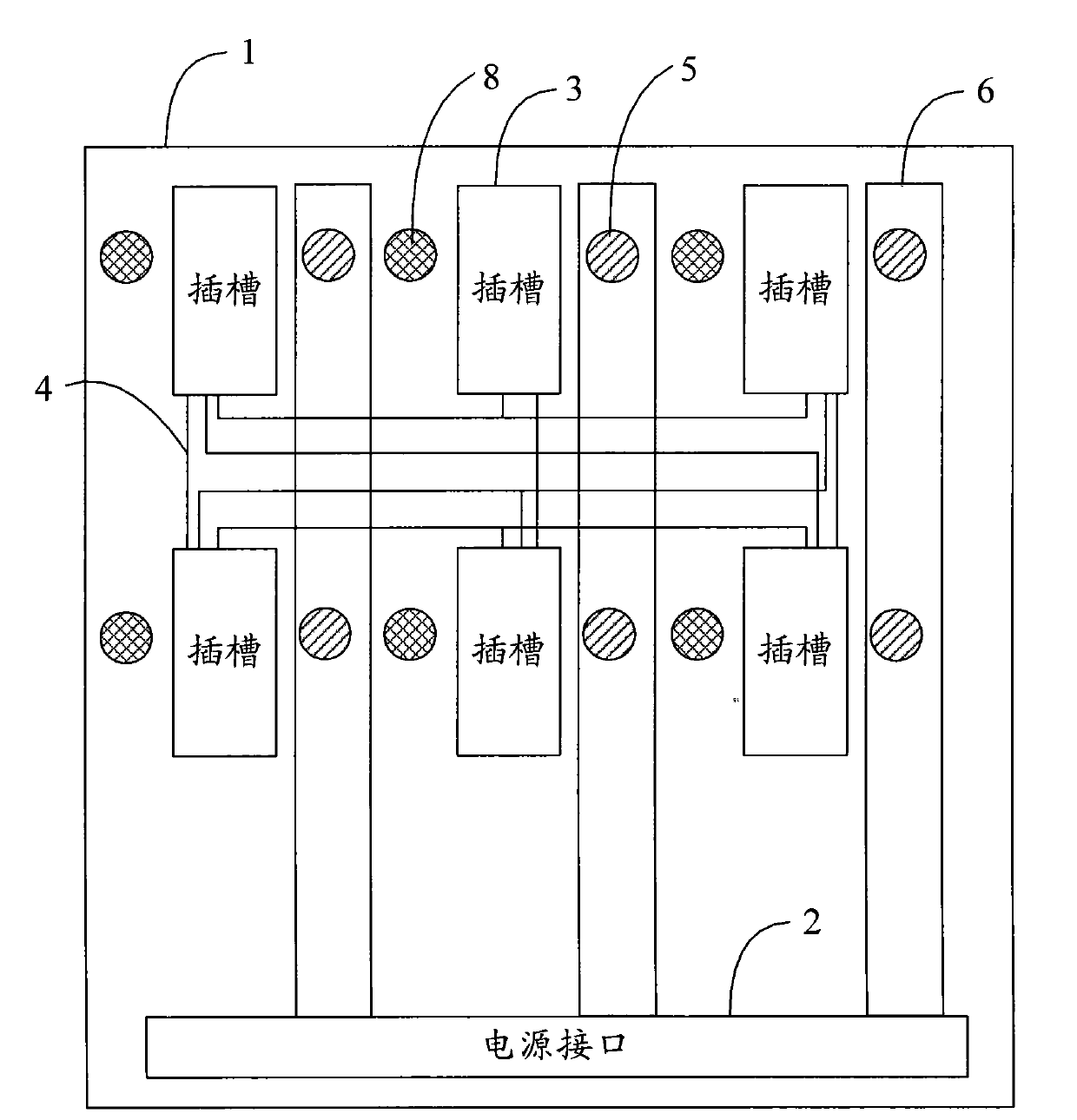
[0028] Figure 3a A schematic top view of a partial structure of the backplane provided by Embodiment 1 of the present invention. Such as Figure 3a As shown, the backplane of this embodiment includes a substrate 1, on which a power interface 2, a plurality of slots 3, a first positioning pin 5, and power wiring 6 are arranged; 4 to connect, where Figure 3a The connecting wiring 4 shown is only a schematic example. The specific layout of the connecting wires 4 is determined by the interconnection relationship between the slots 3 . In this field, the connecting wire 4 is usually a copper wire.

[0029] Wherein, the power interface 2 is used for outputting current, which may be an output port of a power module directly installed on the substrate 1, or an output port of a power connector on the substrate 1 connected to a power connector on the power backplane. This embodiment does not limit the specific implementation of the power interface 2, which may depend on the struct...

Embodiment 2

[0041] Figure 4 A schematic top view of a partial structure of the backplane provided by Embodiment 2 of the present invention. This embodiment is realized based on Embodiment 1, such as Figure 4 As shown, the difference between this embodiment and Embodiment 1 is that a plurality of first positioning pins 5 are provided on one side of each slot 3 on the substrate 1 of this embodiment. Figure 4 Take 2 as an example. Among them, by increasing the number of first positioning pins 5 corresponding to each slot 3, multiple power supply paths can be formed, and the current of each path can be reduced by using multiple power supply paths, thereby improving the overall current carrying capacity. Wherein, the number of the first positioning pins 5 corresponding to each slot 3 can be determined in combination with the actual substrate layout and current requirements.

[0042] In addition, in this embodiment, the current-carrying capacity can be further improved by increasing the w...

Embodiment 3

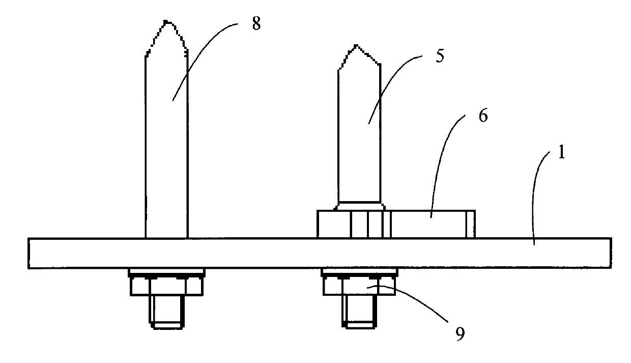
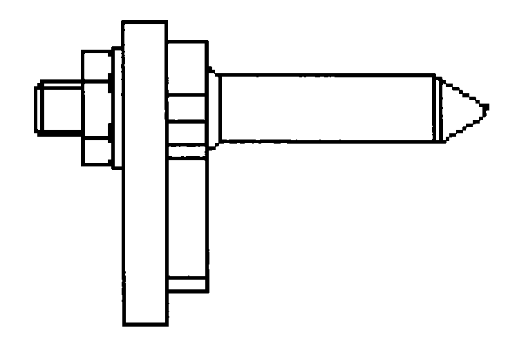
[0044] Figure 5a A schematic top view of the partial structure of the backplane provided by Embodiment 3 of the present invention; Figure 5b A schematic side view of a partial structure of the backplane provided by Embodiment 3 of the present invention. This embodiment can be realized based on the above-mentioned embodiment 1 or embodiment 2, such as Figure 5a and Figure 5b As shown, the difference from the above-mentioned embodiment is that the substrate 1 of this embodiment is also provided with a second positioning pin 8, and the second positioning pin 8 is located on the other side of the slot 3 corresponding to the first positioning pin 5, It is used to provide a ground signal to form a current loop with the first positioning pin 5 .

[0045] Wherein, the first positioning pin 5 in the above-mentioned embodiments of the present invention carries the power signal, and usually a ground signal is required on the backplane, and the ground signal can use the ground sign...


PUM


Abstract

The invention provides a backboard, a board card and a network device. The backboard comprises a substrate, a first locating tab and a power wire, wherein the substrate is provided with a power interface, a plurality of slots and a connecting wire connected among the slots; the first locating tab is arranged on the substrate and at one side of the slot, and is used for matching with a first pilot pin on the board card inserted into the slots to fix the board card; and the power wire is arranged on the surface of the substrate and is separately connected with the power interface and the first locating tab in order to supply power to the board card through the first locating tab and the first pilot pin. Adopting the technical scheme of the invention can ensure that the backboard provides higher currents which does not flow through the substrate, and thus the damage caused by the heat generated by the high currents on the backboard and the interference of the high currents on other signals are reduced.

Description

technical field [0001] The invention relates to a backplane in communication equipment, in particular to a backplane, board and network equipment. Background technique [0002] Modularization refers to the standardization of the interface and size of devices with different performances but the same function or function, and standardized devices are called modules; these modules are placed in a modular chassis and connected with the modular chassis Together they form a modular device, also known as a modular host. Among them, users can choose appropriate modules according to their needs, and install the modules into the modular chassis to realize various functions flexibly and conveniently. [0003] Generally, modules can be divided into management modules, service modules, and power modules according to their functions. Modules with different functions have different functions. For example, the power module is used to provide working current to each module. The modular equ...

Claims


Application Information

Patent Timeline
Patent Type & Authority Applications(China)
IPC IPC(8): H04L12/56H04L12/02H05K7/02H05K7/20
Inventor 肖群黄金思
Owner BEIJING XINWANG RUIJIE NETWORK TECH CO LTD
Why Eureka
Try Eureka