Terminal equipment and communication method for terminal

A technology of a terminal device and a communication method, applied in the field of communication, can solve problems such as difference in service quality, inability to support concurrent PS services, and limitation of application capabilities.

Active Publication Date: 2013-08-28
SPREADTRUM COMM (SHANGHAI) CO LTD
View PDF3 Cites 0 Cited by
  • Summary
  • Abstract
  • Description
  • Claims
  • Application Information

AI Technical Summary

Problems solved by technology

[0005] However, the inventors of the present invention have found that, under actual network conditions, the quality of service provided by networks of different modes or different location areas under the same mode network to the communication services of the same domain (CS domain or PS domain) often differs. There is a big difference, especially when there are concurrent CS and PS services, and it is difficult for terminal equipment to provide a comprehensive and better quality of service by selecting a single cell with a better single network mode
[0006] For example, cells under the GSM network basically cannot support concurrent CS and PS services for the same terminal device; for example, some cells on individual networks can only support one of CS and PS services, but not the other.
[0007] On the other hand, if a terminal device with multi-radio, or dual-mode or even multi-mode simultaneous access capabilities is implemented as a single-card single-pass or multi-card single-pass terminal device form, it also limits its application capabilities.
[0008] As for the single-card dual-pass or multi-card dual-pass mobile terminals, they are still in the research and development stage. Generally speaking, the software and hardware of the original single-pass terminals need to be relatively large-scale transformation, which is more difficult to realize.

Method used


Image

  • Terminal equipment and communication method for terminal
  • Terminal equipment and communication method for terminal
  • Terminal equipment and communication method for terminal

Examples


Embodiment Construction

[0030] In the following description, many technical details are proposed in order to enable readers to better understand the application. However, those skilled in the art can understand that without these technical details and various changes and modifications based on the following implementation modes, the technical solution claimed in each claim of the present application can be realized.

[0031] In order to make the purpose, technical solution and advantages of the present invention clearer, the following will further describe the implementation of the present invention in detail in conjunction with the accompanying drawings.

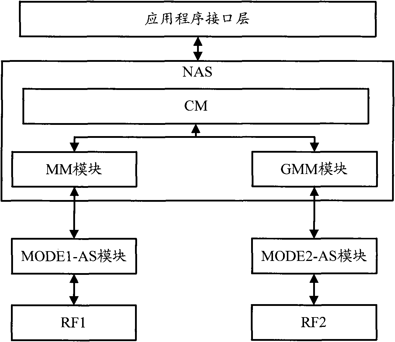
[0032] The first embodiment of the present invention relates to a terminal device. figure 1 It is a structural schematic diagram of the terminal equipment, including: a first radio frequency module, a second radio frequency module, a first access module, a second access module, a mobility management module and a GPRS (General Packet Radio Service)...


PUM


Abstract

The invention relates to the field of communication, and discloses terminal equipment and a communication method for a terminal. In the terminal equipment, the functions of CS and PS services are mutually independent by reforming an MM and a GMM in a non-access layer and removing the correlation between the MM and the GMM on the premise of keeping the implementation mode of an access layer (comprising a physical layer). Therefore, the terminal equipment can perform the operations of residing, receiving broadcast information, initiating services and the like in two different service cells at the same time so as to comprehensively provide good quality of service, and is simple to implement.

Description

technical field [0001] The present invention relates to the field of communications, in particular to terminal equipment in the field of communications. Background technique [0002] With the continuous development of communication technology, various types of wireless communication system network modes have emerged, such as Global System for Mobile communication (Global System for Mobile communication, referred to as "GSM"), Wideband Code Division Multiple Access (Wideband Code Division Multiple Access, WCDMA for short), Time Division Synchronous Code Division Multiple Access (TD-SCDMA for short), Worldwide Interoperability for Microwave Access (WiMAX for short), Long Term Evolution (Long Term Evolution Term Evolution, referred to as "LTE") and so on. [0003] According to the existing 3rd Generation Partnership Project (3rd Generation Partnership Project, referred to as "3GPP") mobile communication standard protocol, the terminal device consists of a Subscriber Identity M...

Claims


Application Information

Patent Timeline
Patent Type & Authority Patents(China)
IPC IPC(8): H04W48/18H04W60/00H04W64/00H04W68/00H04W88/06
Inventor 金逸
Owner SPREADTRUM COMM (SHANGHAI) CO LTD
Why Eureka
Try Eureka