Impeller and turbocharger

A technology for impellers and blades, which is applied in the direction of machines/engines, non-variable pumps, pump components, etc., can solve the problems of increasing the loss of thrust bearings, and achieve the effect of improving the creep life of the impeller and reducing the demand

Inactive Publication Date: 2011-01-19
NAPIER TURBOCHARGERS LTD
View PDF11 Cites 11 Cited by
  • Summary
  • Abstract
  • Description
  • Claims
  • Application Information

AI Technical Summary

Problems solved by technology

[0010] In addition to the additional losses in adding this high pressure cooling air also increases the pressure behind the impeller and increases the thrust load and thus additional thrust bearing losses

Method used


Image

  • Impeller and turbocharger
  • Impeller and turbocharger
  • Impeller and turbocharger

Examples


Embodiment Construction

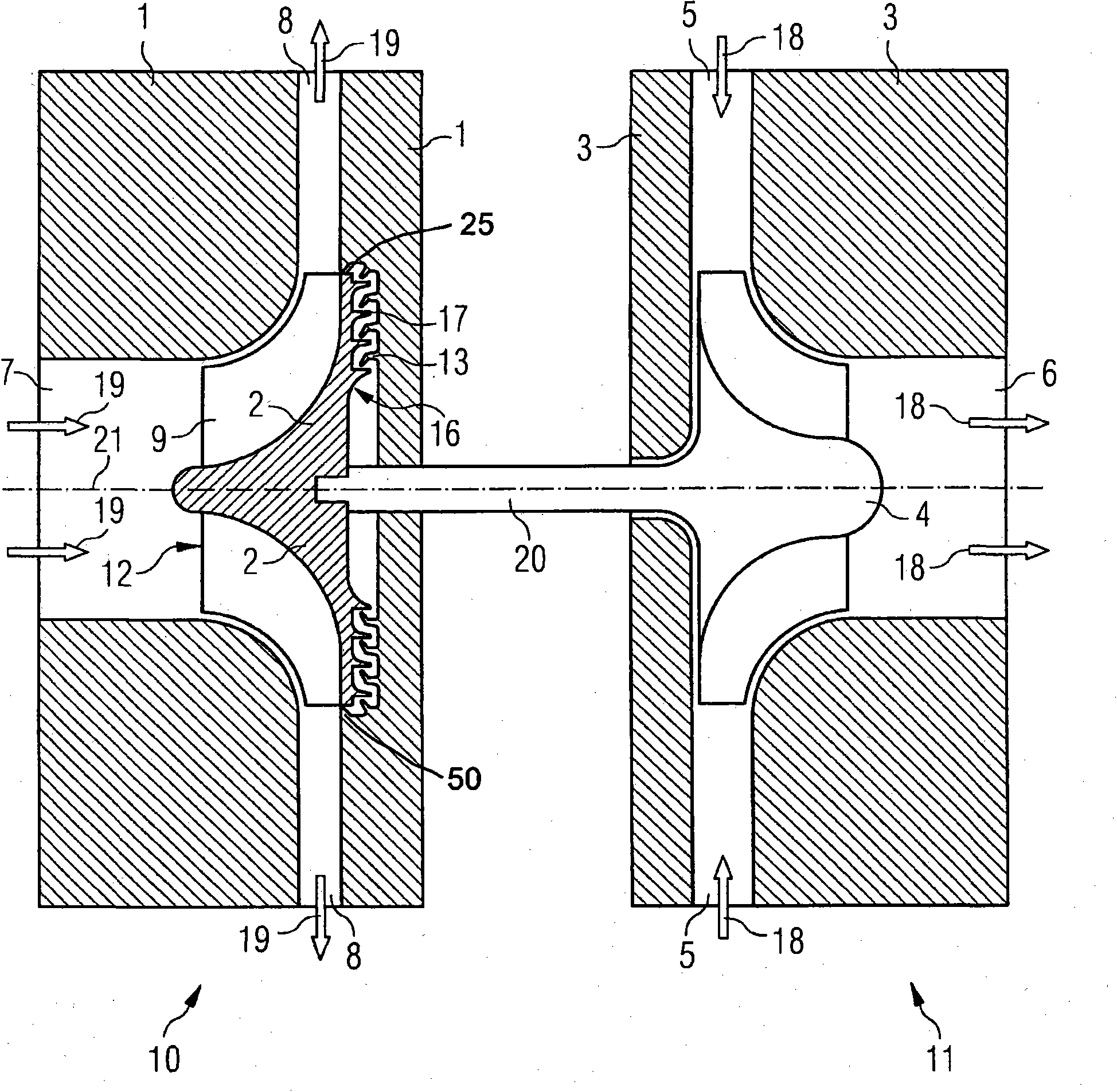
[0030] will refer to below Figure 1 to Figure 4 A first embodiment of the impeller of the present invention and the turbocharger of the present invention will be described. figure 1 The turbocharger is shown schematically in a sectional view. The turbocharger includes a turbine 11 and a compressor 10 . The turbine 11 and the compressor 10 are connected by a shaft 20 .

[0031] The turbine 11 includes a rotor 4 located within a turbine housing 3 . The turbine housing 3 has an exhaust gas inlet 5 to the rotor 4 such that the exhaust gas entering the exhaust gas inlet 5 drives the rotor 4 . Furthermore, the turbine housing 3 has an exhaust outlet 6 through which the exhaust gas from the rotor 4 leaves the turbine housing 3 . Arrow 18 indicates the exhaust gas flow which enters the turbine housing 3 through the exhaust gas inlet 5 , entrains the rotor 4 and leaves the turbine housing 3 through the exhaust gas outlet 6 .

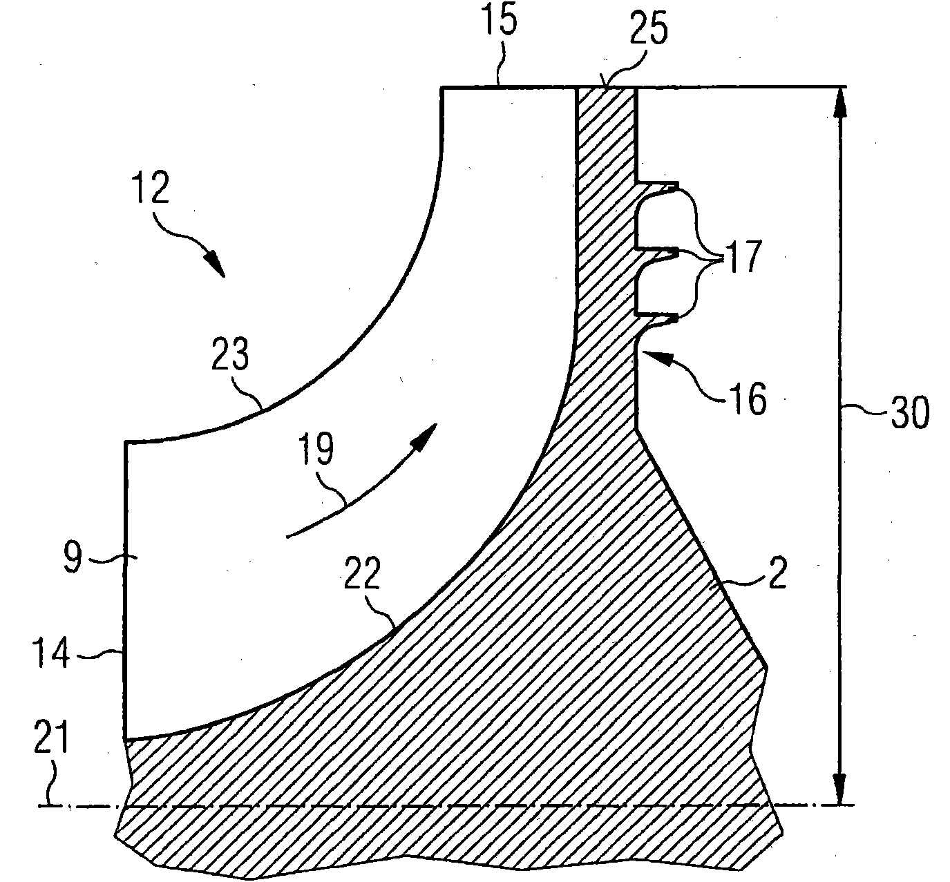
[0032] Compressor 10 includes an impeller 12 located ...


PUM


Abstract

An impeller (112, 212) comprising a rotation axis (21), a radial direction, a backplate (2) and a number of vanes (9) which are connected to the backplate (2) at a line of connection (22) is provided. Each vane (9) comprises an upstream side (14), a downstream side (15) and an outer side (23). The downstream side (15) of each vane (9) comprises an edge portion (27) which is located near the outerside (23). The vanes (9) project radially over the backplate (2) and the downstream side (15) further comprises a connecting portion (24) connecting the edge portion (27) to the backplate (2) and including an angle with the radial direction. The connecting portion (24) comprises a convex rounded portion which is located near the line of connection (22). Moreover, a turbocharger comprising an inventive impeller (112, 212) is disclosed.

Description

technical field [0001] The invention relates to an impeller and a turbocharger. Background technique [0002] Compressor wheels for industrial turbochargers are usually made of aluminum. The material is cheap, easy to machine and light enough that turbo lag is not a major concern. Existing turbocharger wheels for moderate speed diesel engines tend not to have through-drilled holes, as this minimizes stresses in the wheel material and reduces the chances of the wheel failing due to fatigue during its typical 50,000 hour life. possibility. [0003] The life of such impellers tends to be dominated by the creep of the turbine material, limiting the maximum working pressure ratio for typical industrial duty to about 5:1. Creep failure of impellers is associated with areas of high stress and high temperature. The region of highest temperature, and therefore the region where creep life is determined, is at the rear of the impeller near the outer diameter. This is usually the a...

Claims


Application Information

Patent Timeline
Patent Type & Authority Applications(China)
IPC IPC(8): F04D29/28F04D29/30
CPCF04D29/30F04D29/284F05D2240/304
Inventor 弗朗西斯·赫耶斯伊恩·布朗保罗·罗奇敖健培
Owner NAPIER TURBOCHARGERS LTD
Why Eureka
Try Eureka