
Turbine rotor device with cooling and pressing structure

A technology of turbine rotor and compression structure, which is applied in the direction of blade support components, engine components, machines/engines, etc., can solve the problems of reduced service life of turbine rotor, low reliability, high thermal stress, etc., to increase the effective convection area, Increase the space of the cold air channel and reduce the effect of relative slippage

Active Publication Date: 2020-06-26
BEIJING SNECMA SAIC TURBOTECH CO LTD
View PDF8 Cites 0 Cited by
  • Summary
  • Abstract
  • Description
  • Claims
  • Application Information

AI Technical Summary

Problems solved by technology

[0002] Aeroengine turbine rotors usually use fir-tree tenon and tongue-and-groove connection structures to realize the assembly of turbine disks and blades. This structure is an important part of the aeroengine structure, and the rationality of its structural design is directly related to the strength, life and reliability of the rotor components. properties, and greatly affect the thrust-to-mass ratio of the engine. At present, the aero-engine turbine rotor adopts a fir tree-shaped tenon and tenon-groove connection structure. It can reach or even exceed 900K, and generate high thermal stress. At the same time, the fretting friction between the tenon of the blade and the tenon and groove of the wheel will greatly reduce the service life of the turbine rotor
With the continuous improvement of the performance requirements of aero-engines, the working environment of turbine components is becoming more and more harsh. The shortcomings of the traditional fir-tree-shaped tenon-tenon connection structure are more and more obvious, which can no longer meet the high-quality requirements.

Method used


Image

  • Turbine rotor device with cooling and pressing structure
  • Turbine rotor device with cooling and pressing structure
  • Turbine rotor device with cooling and pressing structure

Examples


Embodiment Construction

[0033] Certain terms are used, for example, in the description and claims to refer to particular components. Those skilled in the art should understand that hardware manufacturers may use different terms to refer to the same component. The specification and claims do not use the difference in name as a way to distinguish components, but use the difference in function of components as a criterion for distinguishing. As mentioned throughout the specification and claims, "comprising" is an open term, so it should be interpreted as "including but not limited to". The terms "first" and "second" are used for descriptive purposes only, and cannot be understood as indicating or implying relative importance or implicitly specifying the number of indicated technical features; "plurality" means equal to or more than three ; Subsequent descriptions in the specification are preferred implementation modes for implementing the application, but the descriptions are for the purpose of illustr...


PUM


Abstract

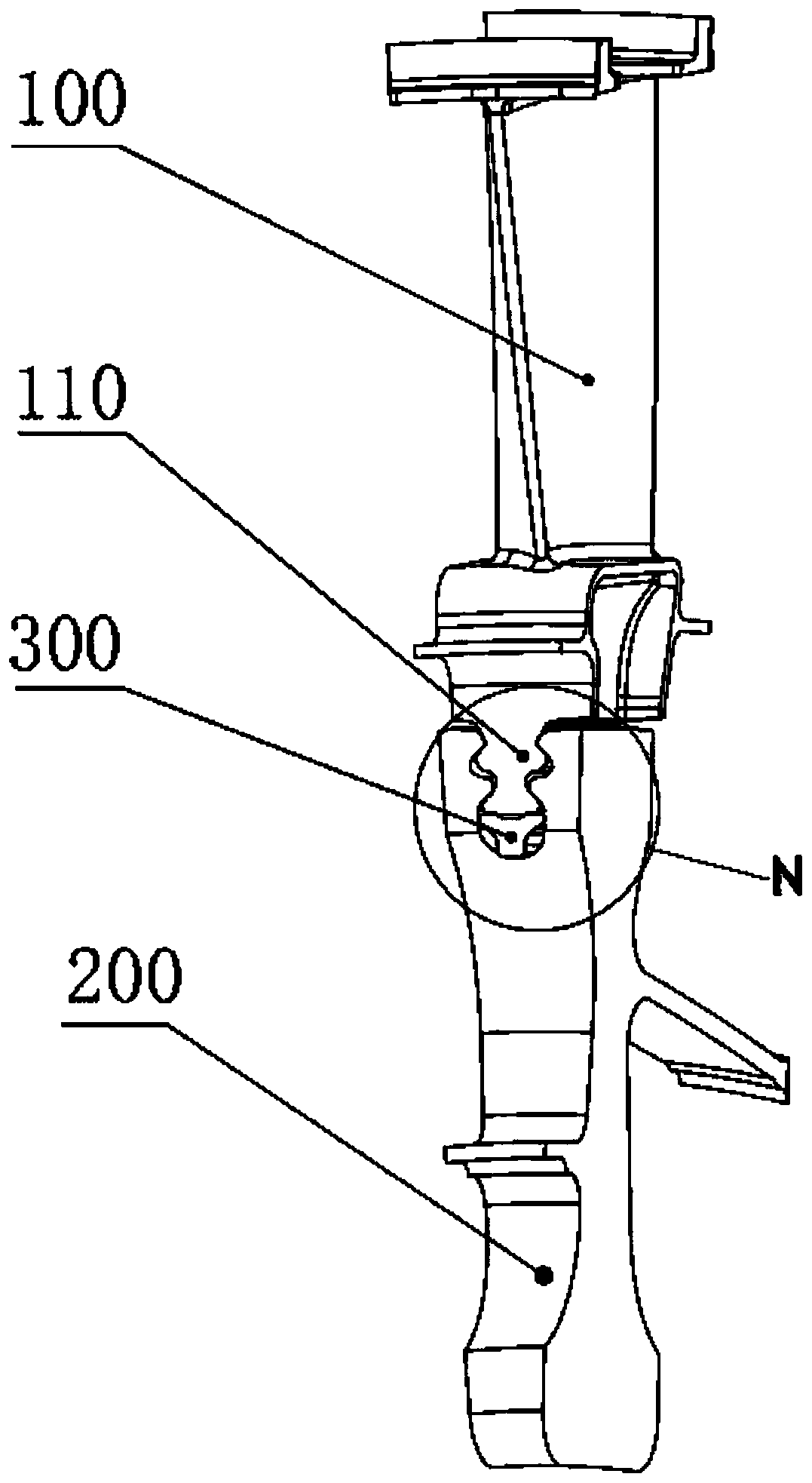
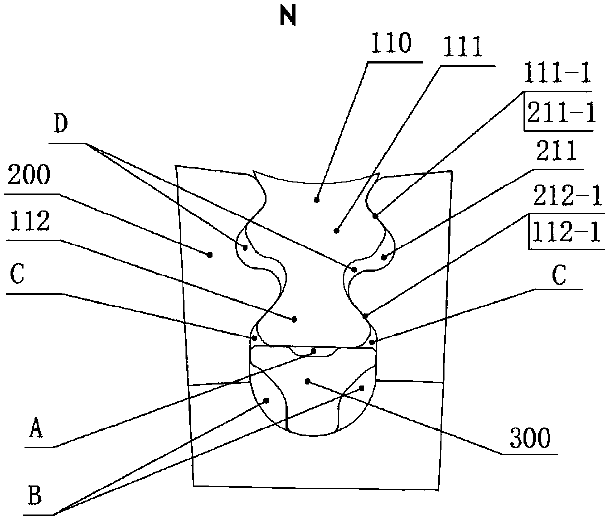
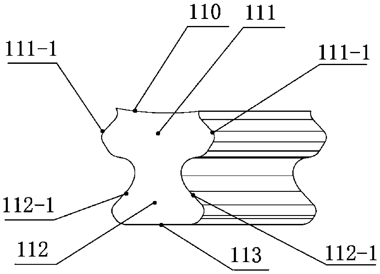
The invention relates to a turbine rotor device with a cooling and pressing structure. The turbine rotor device comprises blades and a wheel disc which are matched and connected through a fir-shaped tenon and a mortise, and further comprises the cooling and pressing device which is arranged in a gap between the end surface of the tenon and the bottom of the mortise in an interference manner, the cooling and pressing device is provided with a lower main supporting column and upper branch supporting columns which are symmetrically arranged. According to the turbine rotor device with the coolingand pressing structure, the main supporting column and the branch supporting columns form a plurality of cold air channels with the tenon tooth end face and the mortise respectively, so that the relative positions of the tenon teeth and the mortise are fixed, the effective convection area of cold air is increased, the space of a cold air channel and the effective convection area are increased, thetemperature of the rim part and the temperature of the joint of the blade tenon and the wheel disc mortise are reduced, the thermal stress of the blade tenon is reduced, and the creep life of the blade tenon, the wheel disc mortise structure and the wheel disc rim is prolonged.

Description

technical field [0001] The invention relates to the technical field of aero-engines, in particular to a turbine rotor device with a cooling compression structure. Background technique [0002] Aeroengine turbine rotors usually use fir-tree tenon and tongue-and-groove connection structures to realize the assembly of turbine disks and blades. This structure is an important part of the aeroengine structure, and the rationality of its structural design is directly related to the strength, life and reliability of the rotor components. properties, and greatly affect the thrust-to-mass ratio of the engine. At present, the aero-engine turbine rotor adopts a fir tree-shaped tenon and tenon-groove connection structure. It reaches or even exceeds 900K, and produces high thermal stress. At the same time, the fretting friction between the tenon of the blade and the tenon and groove of the wheel will greatly reduce the service life of the turbine rotor. With the continuous improvement of...

Claims


Application Information

Patent Timeline
Patent Type & Authority Applications(China)
IPC IPC(8): F01D5/30F01D5/32F01D5/08
CPCF01D5/08F01D5/3007F01D5/326
Inventor 濮睿德段入柯
Owner BEIJING SNECMA SAIC TURBOTECH CO LTD
Learn More