Supercharge Your Innovation With Domain-Expert AI Agents!

Dielectric barrier discharge pump apparatus and method

A technology of blocking discharge and dielectric layer, which is applied in the field of dielectric barrier discharge pump devices, and can solve the problems of physical installation of pumps, large diameters of pipes or conduits, difficulties, etc.

Active Publication Date: 2014-05-14
THE BOEING CO
View PDF4 Cites 0 Cited by
  • Summary
  • Abstract
  • Description
  • Claims
  • Application Information

AI Technical Summary

Problems solved by technology

In some cases it is particularly difficult to use existing pumps or similar
One reason is that it is very difficult to physically install a pump in a pipe or conduit
Another challenge is that the pump may need to be of a physical size that significantly blocks fluid flow through the tubing, or conversely requires that the diameter of the tubing or conduit be unacceptably large
Additionally, existing pumps may be required to be driven by electric motors, which will often have multiple moving parts
The presence of multiple moving parts in the motor or in the pump itself will result in required periodic maintenance and / or repairs which would be difficult and time consuming if the pump were installed in a pipe or conduit
Existing pumps can also be noisy and have significant weight, limiting their use in various applications

Method used


Image

  • Dielectric barrier discharge pump apparatus and method
  • Dielectric barrier discharge pump apparatus and method
  • Dielectric barrier discharge pump apparatus and method

Examples


Embodiment Construction

[0022] The following description is merely exemplary in nature and is not intended to limit the invention, application, or uses. It should be understood that throughout the drawings, corresponding reference numerals indicate similar or corresponding parts and features.

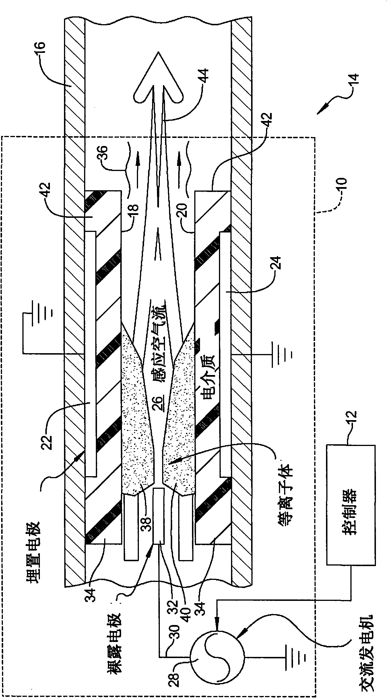
[0023] refer to figure 1 , shows the fluid flow acceleration device 10 . A fluid flow acceleration system 14 is formed using devices connected to the controller 12 . The device 10 may be disposed within a conduit 16 or conduit, or any component or structure in which a contained or semi-contained fluid flow exists, and within which it is desired to accelerate the fluid flow.

[0024] refer again figure 1 , device 10 includes a first dielectric layer 18 affixed to the inner wall of conduit 16, and a second dielectric layer 20 also affixed to the inner wall of conduit 16 in facing (ie opposing) relationship. The first dielectric layer 18 includes a first electrode 22 at least substantially embedded within the...


PUM


Abstract

A dielectric element barrier discharge pump for accelerating a fluid flow. In one embodiment the pump has a first dielectric layer having a first electrode embedded therein and a second dielectric layer having a second electrode embedded therein. The first and second dielectric layers are further supported apart from one another to form an air gap therebetween. A third electrode is disposed at least partially in the air gap upstream of the first and second electrodes, relative to a direction of flow of the fluid flow. A high voltage supplies a high voltage signal to the third electrode. The electrodes cooperate to generate opposing asymmetric plasma fields in the gap that create an induced air flow within the gap. The induced air flow operates to accelerate the fluid flow as the fluid flow moves through the gap.

Description

technical field [0001] The present invention relates generally to a pump and more particularly to a dielectric barrier discharge pump apparatus and method capable of generating a fluid jet through the creation of an asymmetric plasma field without the moving parts typically associated with a fluid pump. Background technique [0002] The statements in this section merely provide background information to which the present disclosure is related and may not constitute prior art. [0003] In many applications, it is desirable to be able to accelerate fluid flow (such as air flow, exhaust flow, gas flow, etc.) in a pipe or other form of restricted area in which the fluid flows, or to create a Fluid jets, or forming jets of fluid for aerodynamic control or propulsion purposes. In some cases, it is particularly difficult to use existing pumps or similar devices. One reason is that it is very difficult to physically install a pump in a pipe or conduit. Another challenge is that t...

Claims


Application Information

Patent Timeline
Patent Type & Authority Patents(China)
IPC IPC(8): H05H1/24
CPCH05H1/24H05H1/2406
Inventor R·S·戴尔J·S·西尔基B·A·奥斯本
Owner THE BOEING CO
Features
  • R&D
  • Intellectual Property
  • Life Sciences
  • Materials
  • Tech Scout
  • Unparalleled Data Quality
  • Higher Quality Content
  • 60% Fewer Hallucinations
Learn More