Paired roller mechanism of computer flat knitting machine
A flat knitting machine and sub-roller technology, used in knitting, weft knitting, textiles and papermaking, etc., can solve the problems of uneven texture, unstable size, and lack of loop pulling force of knitted fabrics, and avoid false tucks. , The effect of improving the pulling force and improving the quality
- Summary
- Abstract
- Description
- Claims
- Application Information
AI Technical Summary
Problems solved by technology
Method used
Image


Examples
Embodiment 1
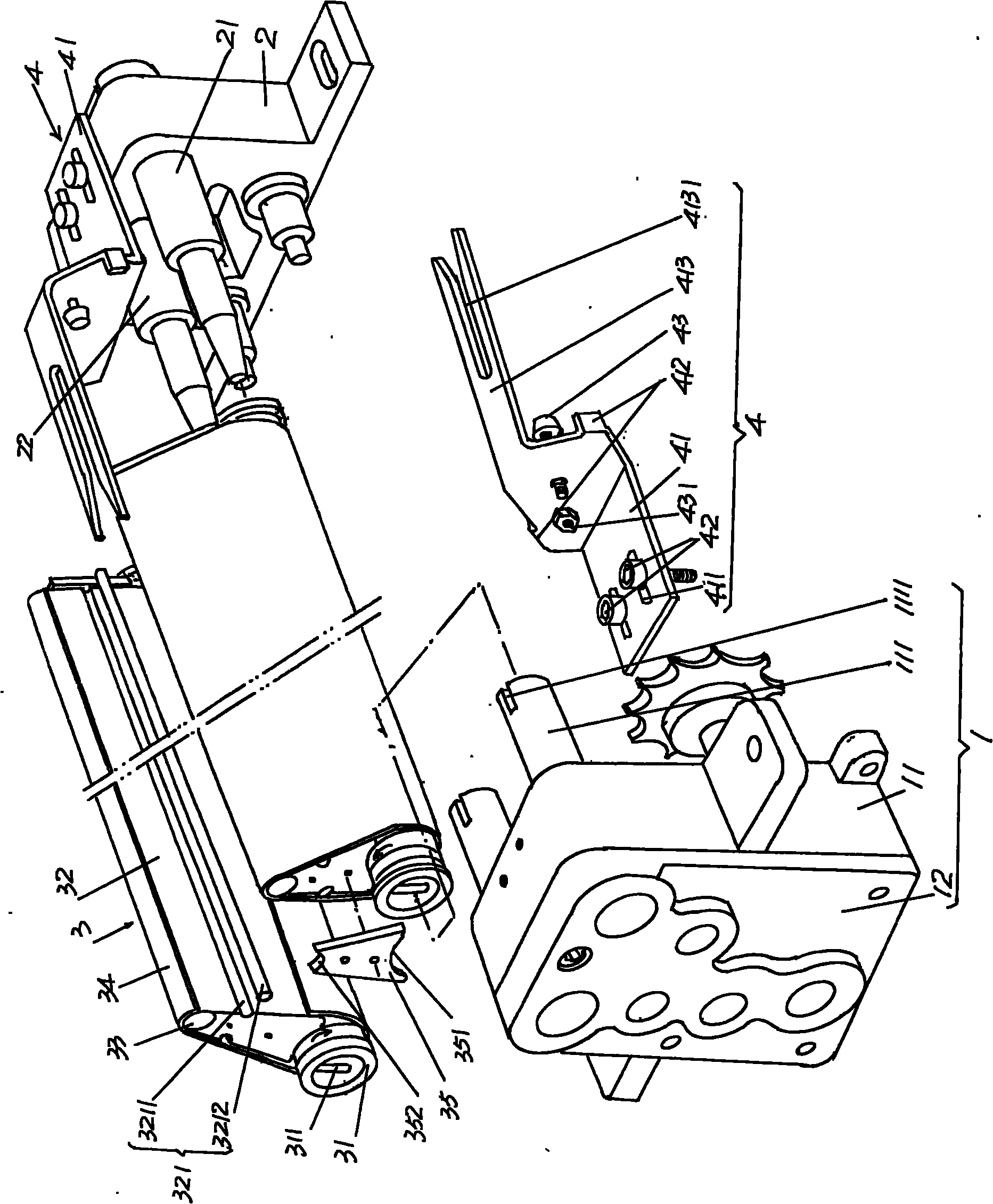
[0027] Please refer to figure 1 , provides a preferred but not absolutely limited power transmission device 1, which is composed of a gear case 11 and a case cover 12, and the case cover 12 is fixed on the opening or the mouth of the gear case 11 by a set of fixing screws. Since the internal structure of the gear box 11 is completely the same as that described by the applicant in the invention patent authorization announcement number CN100554556Y mentioned above and applied by the applicant (the 4th line from the bottom of the 4th page of the specification to the 1st paragraph of the 5th page), Therefore no more detailed description will be given. A pair of power output shafts 111 of the gearbox 11 are in drive connection with the braid pulling device 3 to be described below, and each power output shaft 111 is provided with a tongue and groove 1111 .
[0028] see you later figure 1 , the number of parts and the installation relationship of a pair of braided fabric traction...
Embodiment 2
[0033] please see figure 2 and combine figure 1 As a preferred tensioning device 321 for the cloth sleeve, a semi-arc groove 3211 and a tensioning roller 3212 arranged in the semi-arc groove 3211 are recessed on the corresponding two sides of the upper part of the transition rod support member 32, Preferably, the depth of the semicircular groove 3211 is half of the diameter of the tension roller 321 . This program can make the surface of cloth cover 34 and braid 8 ( Figure 4 Shown) form an angle α of about 3-5°. All the other are the same as the description to embodiment 1.
Embodiment 3
[0035] please see image 3 , as another preferred structure of the tensioning device 321 for the cloth sleeve, half arc protrusions 3213 protrude outward on the corresponding two sides of the upper part of the transition rod support member 32, and the structure of this embodiment can be abandoned in Embodiment 2. The tension roller 321 (also called the small shaft), more precisely, this embodiment has the same effect as embodiment 2. All the other are the same as the description to embodiment 1.
[0036] Please refer to figure 2 , the present invention consists of figure 1 The sub-roller mechanism shown is installed on the inside upper part of a pair of needle beds 6 that generally form a figure-eight and is close to the bottom of the barrel mouth 7 of the knitting mechanism. Specifically, the gear box is fixed by screws 11. The support 2 and the needle bed 6 are fixed.
[0037] applicant combined figure 1 and figure 2 Briefly describe the application of the present ...
PUM
 Abstract
Description
Claims
Application Information
 - R&D
- Intellectual Property
- Life Sciences
- Materials
- Tech Scout
- Unparalleled Data Quality
- Higher Quality Content
- 60% Fewer Hallucinations
Browse by: Latest US Patents, China's latest patents, Technical Efficacy Thesaurus, Application Domain, Technology Topic, Popular Technical Reports.
© 2025 PatSnap. All rights reserved.Legal|Privacy policy|Modern Slavery Act Transparency Statement|Sitemap|About US| Contact US: help@patsnap.com