Energy-saving gas stove with thermal radiation net structure

A heat radiation and gas furnace technology, applied in the direction of heating fuel, gaseous heating fuel, household cooking utensils, etc., to achieve the effect of reducing the discharge rate, improving the utilization rate of heat energy, and smoothing the fire

Inactive Publication Date: 2012-01-04
宁波科莱尔节能科技股份有限公司
View PDF2 Cites 0 Cited by
  • Summary
  • Abstract
  • Description
  • Claims
  • Application Information

AI Technical Summary

Problems solved by technology

But the combustion net is only used in the blast furnace head, and it simply plays the role of wind protection

Method used


Image

  • Energy-saving gas stove with thermal radiation net structure
  • Energy-saving gas stove with thermal radiation net structure
  • Energy-saving gas stove with thermal radiation net structure

Examples


Embodiment 1

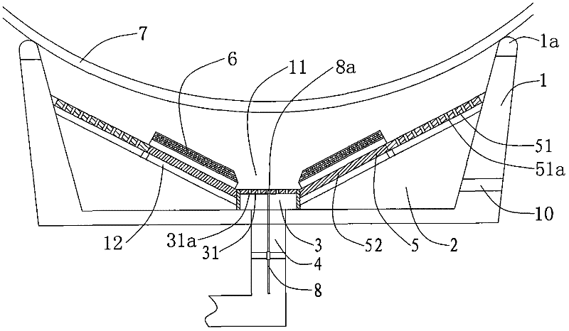
[0035] Such as figure 1 The shown energy-saving gas stove with a heat radiation net structure includes a furnace body 1 , a blast furnace head 3 located in the furnace body cavity 2 , and a mixed gas pipe 4 communicating with the blast furnace head 3 . The upper end surface of the furnace body 1 is formed with a sealing support portion 1a which is sealed and fitted with the bottom of the pot body 7 . A thermal insulation layer 5 is arranged between the inner wall of the furnace body 1 and the blast burner head 3, and the thermal insulation layer 5 divides the inner chamber of the furnace body 2 into upper and lower parts. The surface of the outer ring of the heat insulation layer 5 is formed with a through hole 51a that communicates with the upper and lower parts of the furnace body cavity 2, and the top of the through hole 51a is formed with a horn-shaped opening. At least one heat radiation mesh layer 6 is fixedly arranged above the heat insulation layer 5 . The lower part...

Embodiment 2

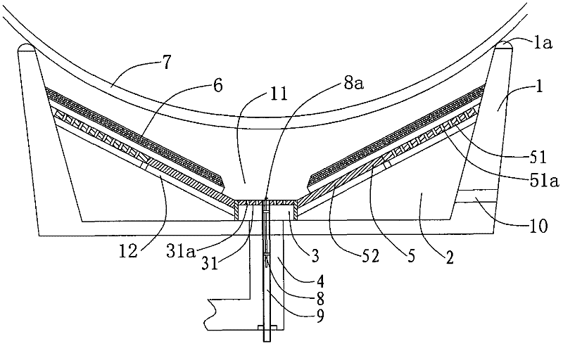
[0045] In this embodiment, the energy-saving gas stove with heat radiation net structure is as follows: figure 2 As shown, it includes a furnace body 1 , a blast furnace head 3 located in the furnace inner chamber 2 , and a mixed gas pipe 4 communicating with the blast furnace head 3 . The upper end surface of the furnace body 1 is formed with a sealing support portion 1a which is sealed and fitted with the bottom of the pot body 7 . A thermal insulation layer 5 is arranged between the inner wall of the furnace body 1 and the blast burner head 3, and the thermal insulation layer 5 divides the inner chamber of the furnace body 2 into upper and lower parts. A through hole 51a connecting the upper and lower parts of the furnace body cavity 2 is formed on the surface of the outer ring of the heat insulation layer 5, and at least one layer of heat radiation mesh layer 6 is fixedly arranged above the through hole 51a. The lower part of the inner cavity 2 of the furnace is provided...

Embodiment 3

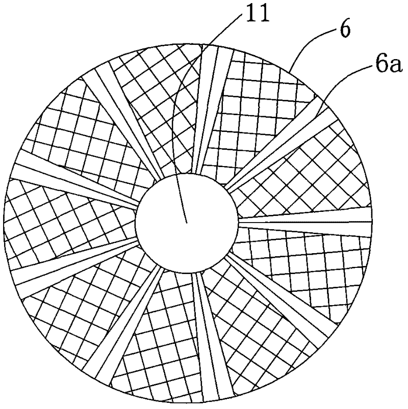
[0051] This embodiment is on the body of furnace structure of embodiment 1 or embodiment 2, adopts Figure 5 Heat radiation mesh layer 6 is shown. The heat radiation mesh layer 6 can be made integrally, or can be composed of multiple pieces of heat radiation mesh units 61 spliced ​​together.

[0052] The heat radiation mesh layer 6 of the present embodiment is concentric wave ring, as Figure 5a In the sectional view shown, the heat radiation net unit 61 is wavy from the center to the outside, and the lower surface forms a supporting edge 61a, which is placed on the heat insulation layer 5, at least covering the outer ring of the heat insulation layer 5, and can also cover Whole thermal insulation layer 5. After the gas burns, since the heat radiation mesh layer 6 is located between the heat insulation layer 5 and the pot body 7, the heat flow will pass through the screen mesh of the heat radiation mesh layer 6, thereby fully heating the heat radiation mesh layer 6 and turni...


PUM


Abstract

The invention discloses an energy-saving gas stove with a thermal radiation net structure. The energy-saving gas stove with the thermal radiation net structure comprises a stove body, a blast furnace head and a mixed gas pipe, wherein the blast furnace head is positioned in the inner cavity of the stove body; the mixed gas pipe is communicated with the blast furnace head; a seal supporting part hermetically matched with the bottom of a boiler body is arranged on the upper end face of the stove body; an insulating layer is arranged between the inner wall of the stove body and the blast furnacehead; the inner cavity of the stove body is divided into an upper part and a lower part by the insulating layer; a through hole for communicating the upper part with the lower part of the inner cavity of the stove body is formed in the surface of an outer ring of the insulating layer; at least one thermal radiation net layer is fixedly arranged above the through hole; and the lower part of the inner cavity of the stove body is provided with a smoke channel communicated with the outside. The energy-saving gas stove with the thermal radiation net structure has the advantage of greatly increasing the heat energy utilization ratio of the gas by heating the boiler body again by utilizing heat stored in exhaust through the insulating layer and the thermal radiation net structure.

Description

technical field [0001] The invention relates to a large-scale energy-saving gas stove used in canteens and restaurants, in particular to an energy-saving gas stove with a heat radiation net structure. Background technique [0002] The heating principle of the traditional stove is to heat the bottom of the pot by directly burning gas through the atmosphere. Although such a heating method can also achieve the purpose of heating the food in the pot, due to the limitation of the area of ​​the bottom of the pot, the local flame cannot be fully utilized, and part of the heat overflows through the gap between the bottom of the pot and the stove, thereby resulting in a waste of energy. [0003] Utility model patent: an energy-saving stove, patent number: 200620140985.9 discloses an energy-saving stove, the energy-saving stove includes the edge of the upper mouth of the stove cavity installed on the stove body to support the pot body, and the middle part of the stove cavity Combust...

Claims


Application Information

Patent Timeline
Patent Type & Authority Patents(China)
IPC IPC(8): F24C3/04F24C3/08F24C15/24
CPCY02B40/166Y02B40/00
Inventor 陈立德
Owner 宁波科莱尔节能科技股份有限公司
Why Eureka
Try Eureka