
Array substrate maintenance equipment and method

A technology for array substrates and maintenance equipment, which is applied in the field of maintenance equipment for TFT-LCD array substrates, can solve problems such as time-consuming, labor-intensive, and low efficiency, and achieve the effect of improving efficiency

Inactive Publication Date: 2013-04-03
BOE TECH GRP CO LTD +1
View PDF0 Cites 0 Cited by
  • Summary
  • Abstract
  • Description
  • Claims
  • Application Information

AI Technical Summary

Problems solved by technology

[0010] The laser energy measurement equipment measures the final laser energy output by the array substrate maintenance equipment. Even if an abnormality in the laser energy is found, it is impossible to determine which link has the problem. Instead, the entire optical path needs to be confirmed one by one, so the abnormality can be ruled out. The process is time-consuming and labor-intensive, and the efficiency is very low

Method used


Image

  • Array substrate maintenance equipment and method
  • Array substrate maintenance equipment and method
  • Array substrate maintenance equipment and method

Examples


Embodiment Construction

[0026] In order to improve the energy detection efficiency of the laser light generated by the equipment, the embodiments of the present invention provide an array substrate maintenance equipment and method.

[0027] The array substrate maintenance equipment provided by the embodiments of the present invention will be described in detail below with reference to the accompanying drawings.

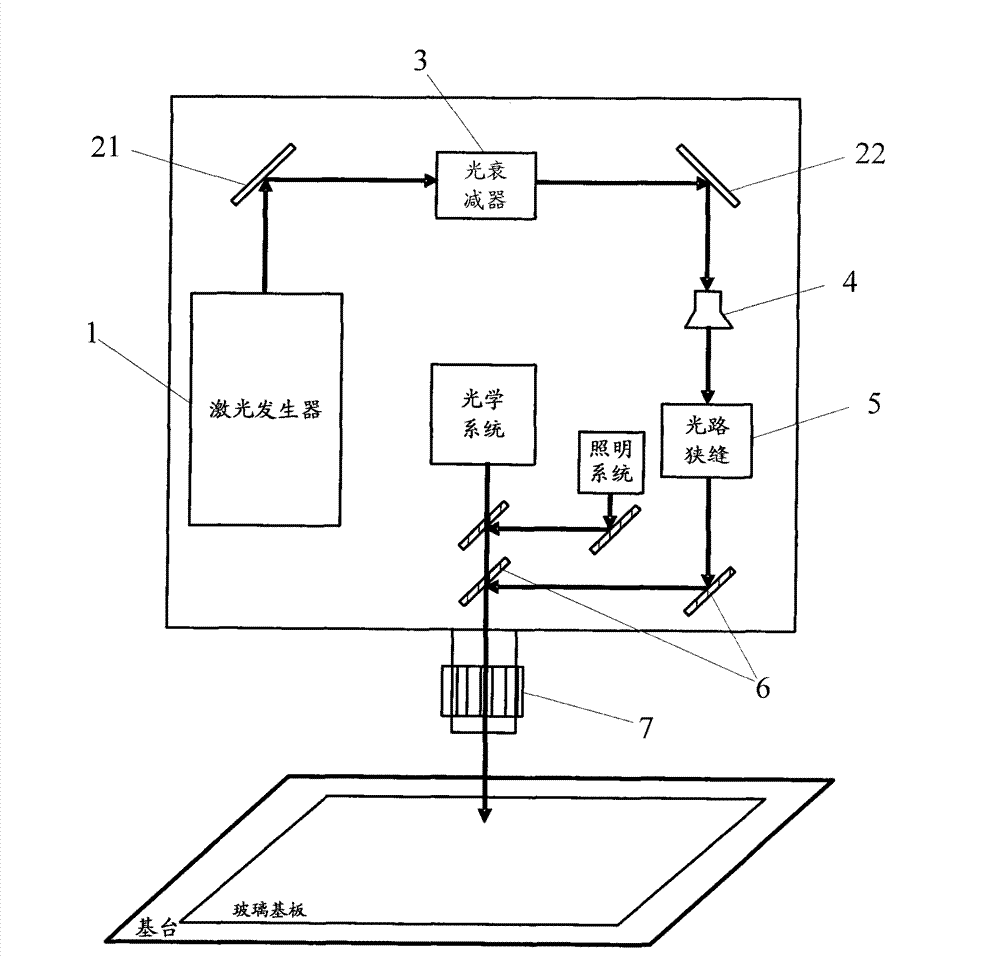
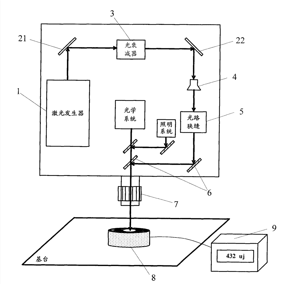
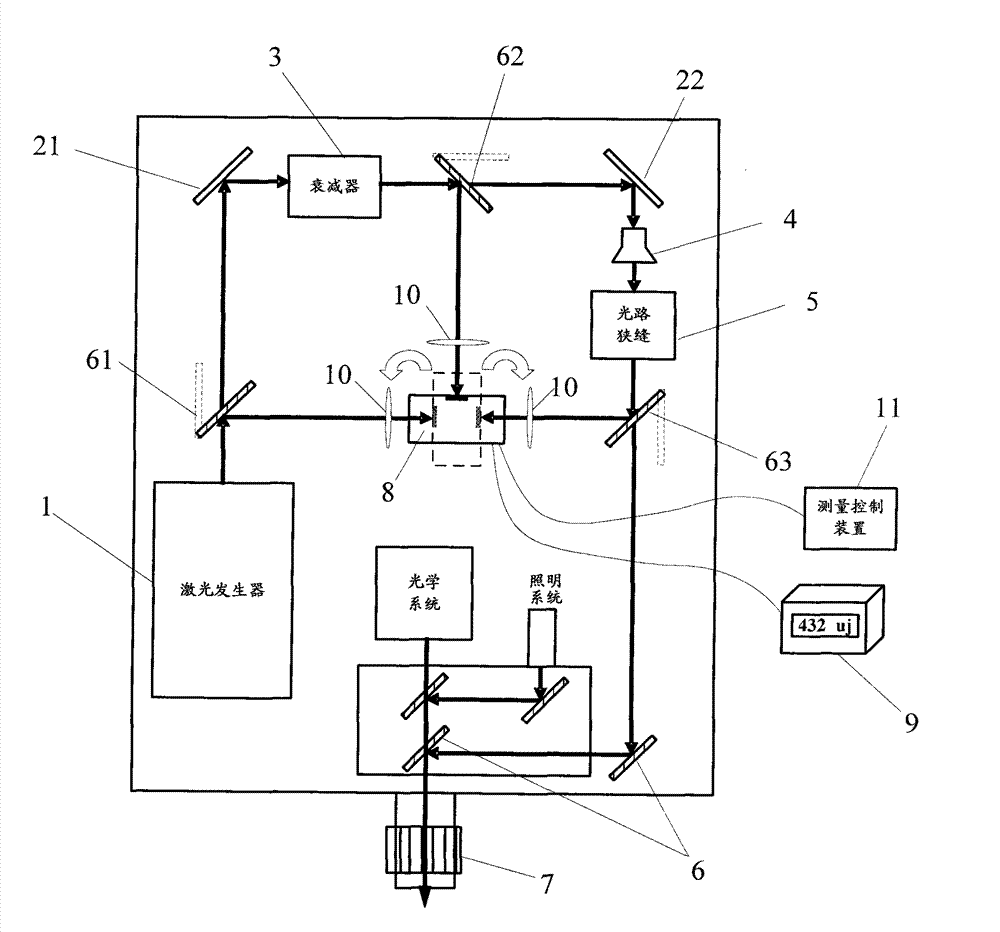
[0028] Such as image 3 As shown, the array substrate maintenance equipment provided by the embodiment of the present invention includes a laser generator 1 for generating laser light, and a beam splitter 21, an optical attenuator 3, a beam splitter 22, and an optical beam expander that are sequentially distributed on the laser optical path. 4. Optical path slit 5 and objective lens 7;

[0029] In addition, in the array substrate maintenance equipment provided in the embodiment of the present invention, between the laser generator 1 and the optical attenuator 3, between the optical attenuat...


PUM


Abstract

The embodiment of the invention discloses array substrate maintenance equipment and an array substrate maintenance method, relates to the technical field of the production of liquid crystal display panels, and can improve the energy detection efficiency of laser generated by equipment. The array substrate maintenance equipment provided by the embodiment of the invention comprises a laser generator, and an optical attenuator, a light beam expander, a light path slit and an objective lens arranged on a laser path in turn, wherein a rotary reflecting mirror is respectively arranged between the laser generator and the optical attenuator, between the optical attenuator and the light beam expander and between the light path slit and the objective lens; and the laser reaches a laser energy measuring probe arranged in the array substrate maintenance equipment after being reflected by the rotary reflecting mirrors. The array substrate maintenance equipment and the array substrate maintenance method provided by the invention are suitable for maintaining a thin film transistor-liquid crystal display (TFT-LCD) array substrate.

Description

technical field [0001] The invention relates to the technical field of liquid crystal display panel production, in particular to a maintenance equipment and method for a TFT-LCD array substrate. Background technique [0002] TFT-LCD (Thin Film Transistor-Liquid Crystal Display, Thin Film Transistor-Liquid Crystal Display) array substrate is to form an array circuit on a glass substrate; after the formation of the array circuit or during the formation process, the formation process needs to be tested; if the test results show If there is a defect in the product, such as a point defect or a line defect, it is necessary to repair the defect. [0003] There are two main situations for bad repairs: one is to disconnect (open) bad repairs, the main method is: the raw material used for repairs is metal carbide powder, and argon (Ar) is used to carry this powder to the In the reaction kettle, the laser is used as the energy source to decompose the above compound through photochemic...

Claims


Application Information

Patent Timeline
Patent Type & Authority Patents(China)
IPC IPC(8): G02F1/1362G02B27/00
Inventor 葛兴田震寰
Owner BOE TECH GRP CO LTD
Learn More