Suction type optical disc drive

A kind of optical disc drive and suction-type technology, which is applied in the direction of recording information storage, instruments, etc., can solve the problems of shortening the life of electronic parts, unable to test points and maintenance positions, and is not conducive to the thinning of the suction-type optical disc drive.

Inactive Publication Date: 2011-01-26
QUANTA STORAGE INC
View PDF1 Cites 2 Cited by
  • Summary
  • Abstract
  • Description
  • Claims
  • Application Information

AI Technical Summary

Problems solved by technology

[0005] However, when the advancing unit 15 pushes the optical disc 16, the contacted peripheral edge is more biased toward the ejecting unit 17, and cannot apply force symmetrically between the ejecting unit 17 and the positioning unit 19, which will easily cause the central hole 20 of the optical disc 16 to be out of position. Aligning the spindle motor 12
In addition, the connecting rods of the ejection unit 17 and the positioning unit 19 are moving up and down the base plate 18, and the opening 23 can only be dug in a limited space outside the moving range of the ejection unit 17 and the positioning unit 19, and it is often impossible to align the main board 22. For the test points and maintenance positions of electronic components, the slot-in optical disk drive 10 must be disassembled to test and repair smoothly, which

Method used


Image

  • Suction type optical disc drive
  • Suction type optical disc drive
  • Suction type optical disc drive

Examples


Embodiment Construction

[0081] In order to achieve the above object, the present invention adopts the technical means and its effects, hereby give preferred embodiments, and illustrate as follows in conjunction with the accompanying drawings.

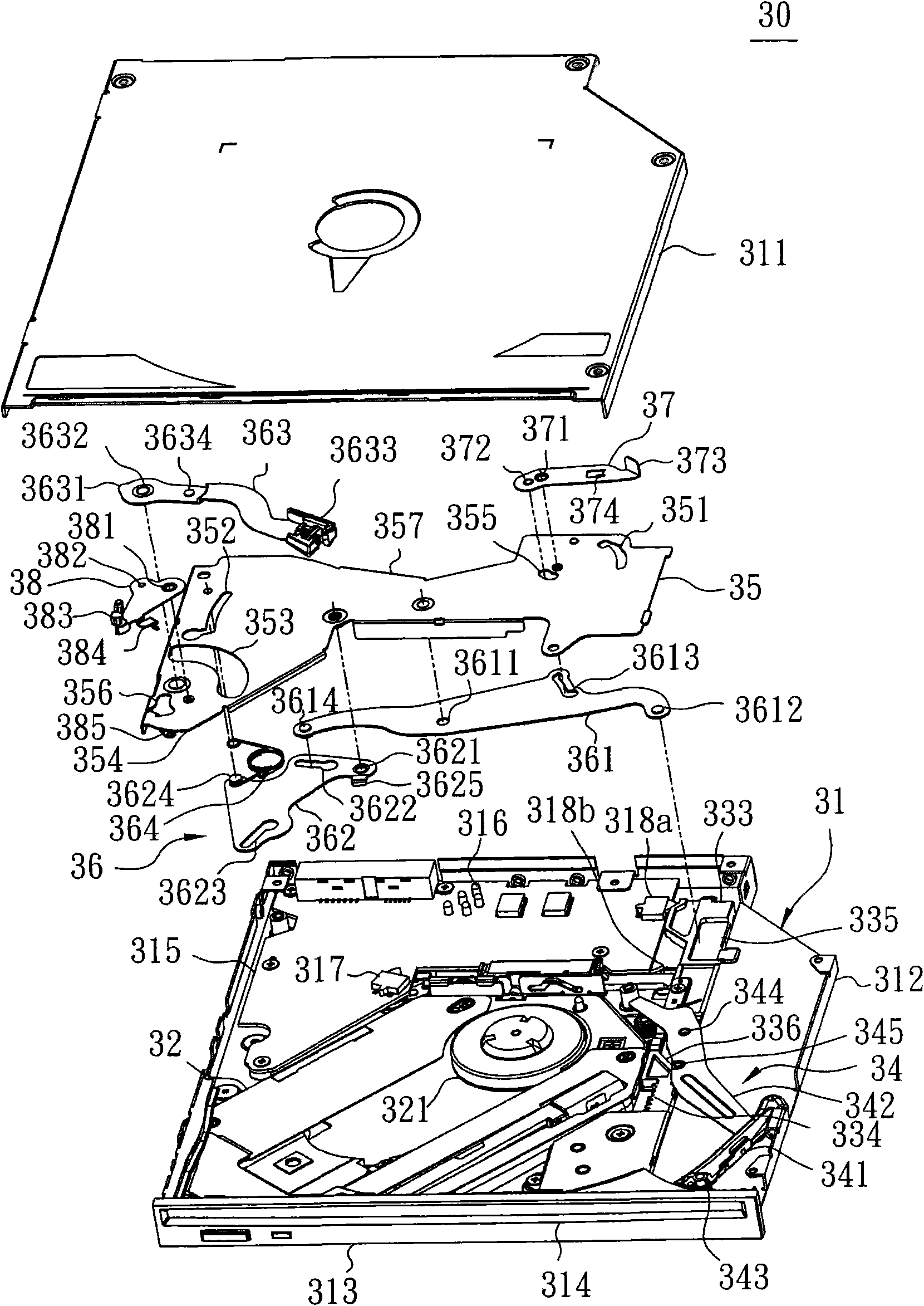
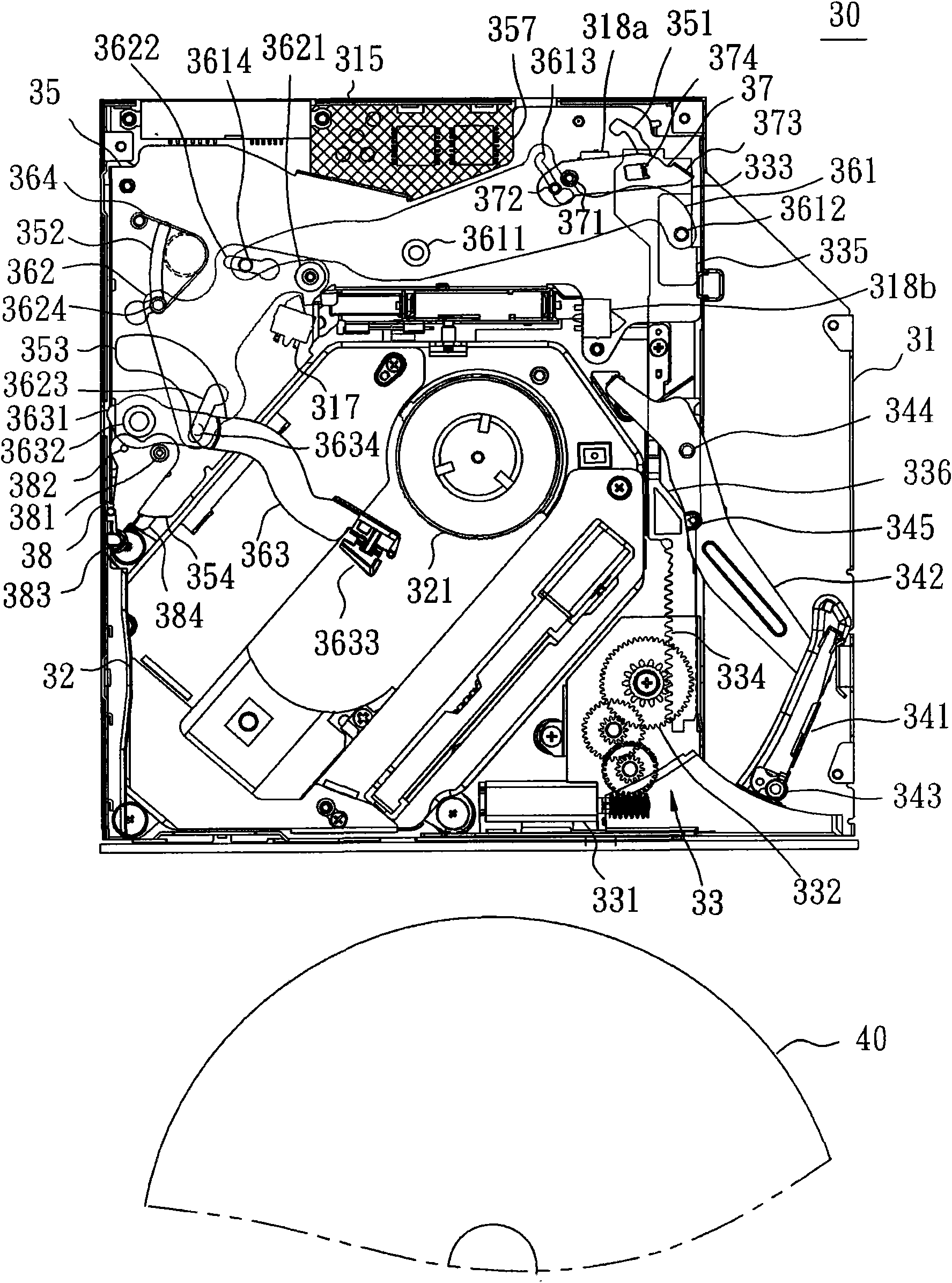
[0082] Please also refer to figure 2 and image 3 , figure 2 It is an exploded view of the parts of the slot-in optical disk drive 30 of the present invention, image 3 It is a top view of the combination of the slot-in disc drive 30 of the present invention. The slot-in disc drive 30 includes a housing 31 , a core 32 , a power unit 33 , a film advance unit 34 , a base plate 35 , a film eject unit 36 ​​, a right positioning rod 37 and a left positioning rod 38 . Wherein, the housing 31 includes an upper shell 311 and a lower shell 312 , has a hollow interior, a front panel 313 is provided, and an inlet and outlet 314 is provided on it for the optical disc 40 to enter and exit. A main board 315 is provided at the bottom of the rear side of the casing 31, ...


PUM


Abstract

The invention discloses a suction type optical disc drive. A sliding piece is driven by a power unit to drive a driving rod to rotate a disc-taking guiding rod to take a disc; a substrate is covered on a mainboard on the back side of a housing; the middle part of a first transmission rod is pivoted in the centre of the substrate; one end of the first transmission rod is drawn by the sliding piece; the first transmission rod is provided with a traction groove to drive a right positioning rod; the other end of the first transmission rod drives a second transmission rod which is pivoted on the substrate; the second transmission rod is fixed at one end of a returning spring and drives a disc-returning guiding rod which is pivoted on the substrate; a cam is arranged at the periphery of one end of the disc-returning guiding rod to drive a left positioning rod, is limited by a positioning spring, and approaches to the side of the housing so as to expose a gap on the back side of the substrate. By arranging the left and right positioning rods symmetrically and separately on the two sides of the disc-returning guiding rod, reducing the moving ranges of the left and right positioning rods and applying force with the disc-taking guiding rod symmetrically, the optical disc positioning guidance is facilitated.

Description

technical field [0001] The invention relates to an optical disc drive for reading and writing optical disc data, in particular to a slot-in optical disc drive for guiding and driving the optical disc into or out of the optical disc drive. Background technique [0002] Generally, there are mainly two types of disc loading methods for optical disc drives: Tray Type and Slot-in Type. A tray-type optical disc drive utilizes a slot on a tray to carry optical discs, which are pushed in or out of the optical disc drive to allow the optical discs to be positioned or ejected. As for the slot-in type CD drive, as long as the CD is directly inserted into the inlet and outlet, the CD can be automatically pushed in through the advancing and retreating mechanism, and the CD can be guided to the position. development trend. [0003] Such as figure 1 As shown, it is the background technology of China Taiwan Publication No. 200805260 "Slot-in Disc Device" patent case, in which a core 11 i...

Claims


Application Information

Patent Timeline
IPC IPC(8): G11B17/051
Inventor 蔡耀庆吴仁琛
Owner QUANTA STORAGE INC
Why Eureka
Try Eureka