

Heating furnace
A heating furnace and furnace body technology, applied in the field of heating furnaces, can solve problems such as poor sealing of furnace doors and damage to furnace bricks, and achieve the effects of good sealing, improving thermal efficiency and prolonging heat transfer time.
- Summary
- Abstract
- Description
- Claims
- Application Information
AI Technical Summary
Problems solved by technology
Method used
Image

Examples
Embodiment Construction
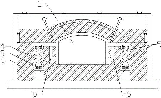
[0055] see figure 1 , the present invention relates to a regenerative heating furnace with a circulation channel, comprising a furnace body 1, a furnace chamber 2, a furnace door and a furnace door sealing structure, a pair of regenerator chambers 4 and a pair of circulation chambers are arranged in the furnace body 1 Channel 6, the circulation channel 6 is on the inside, the regenerator 4 is on the outside, one end of the circulation channel 6 communicates with the regenerator 4, and the other end communicates with the lower part of the furnace 2, and the inner wall of the regenerator 4 is arranged with a separation layer from top to bottom 5. The heat storage chamber 4 is filled with heat storage balls 3 .
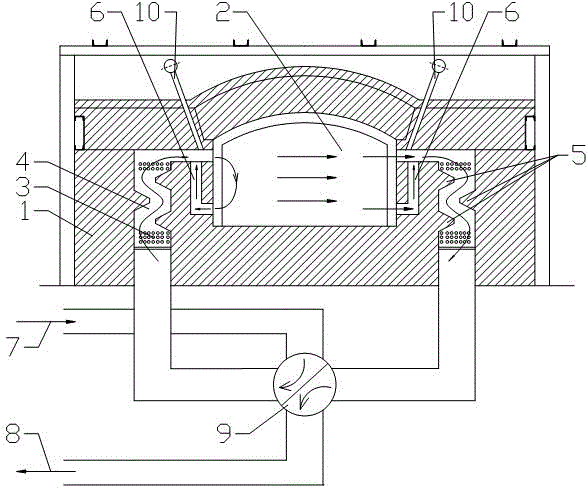
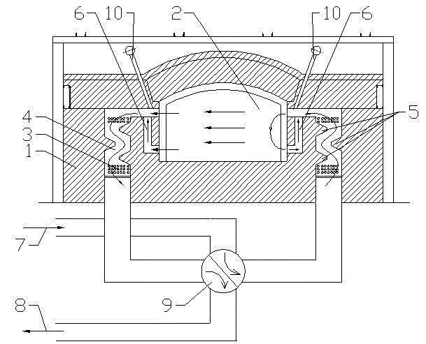
[0056] Working principle of heating furnace:
[0057] Working condition one: see figure 2 , the reversing valve 9 turns to the position shown in the figure, and the air 7 enters figure 2 The heat storage chamber 4 on the left side of the center exchanges heat with t...
PUM
 Abstract
Description
Claims
Application Information