Regenerative heating furnace with gas turnover pipelines

A heating furnace and regenerative technology, which is applied to lighting and heating equipment, furnaces, furnace types, etc. problem, to achieve the effect of good preheating effect, good sealing performance and not easy to be damaged

Inactive Publication Date: 2018-09-28
刘畅
View PDF3 Cites 0 Cited by
  • Summary
  • Abstract
  • Description
  • Claims
  • Application Information

AI Technical Summary

Problems solved by technology

[0003] The existing heating furnace has the following problems: 1) The flue gas passage of the existing regenerative heating furnace is at the upper part of the furnace, and since there is no gas circulation pipeline, when the workpiece is heated in the furnace, the temperature of the workpiece at the upper part of the furnace is high, The temperature of the workpiece located in the lower part of the furnace is low, and the uneven heating of the workpiece will affect the product quality. At the same time, the flue gas located in the lower part of the furnace is difficult to discharge, which affects the thermal efficiency of the regenerative heating furnace; 2) Most of the existing heating furnace doors are locked by nuts , so that the heat-resistant bricks on the inner side of the furnace door are closely attached to the furnace wall. Since there is no limit device on the furnace wall, the bonding force between the heat-resistant bricks and the furnace wall is too large. After the furnace door is frequently used, the distance between the heat-resistant bricks and the furnace wall The contact part will be damaged, which will lead to poor sealing of the furnace door, affect the thermal efficiency of the heating furnace, and even cause safety hazards; 3) After the heating furnace has been used for a long time, the heat-resistant plate of the furnace door at the contact between the furnace door and the furnace mouth will It is easy to be damaged, which will cause the furnace door to be not tightly sealed, making the thermal efficiency of the heating furnace low

Method used


Image

  • Regenerative heating furnace with gas turnover pipelines
  • Regenerative heating furnace with gas turnover pipelines
  • Regenerative heating furnace with gas turnover pipelines

Examples


Embodiment 1

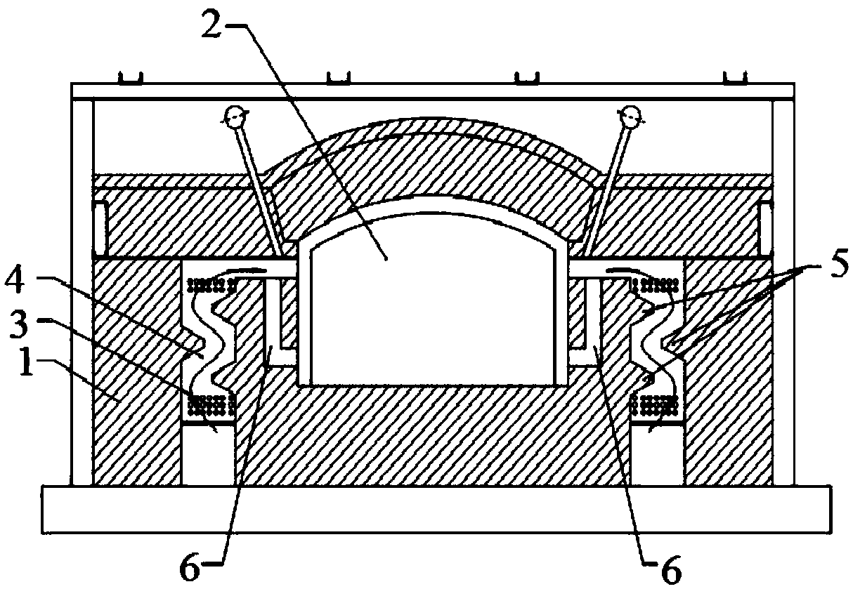
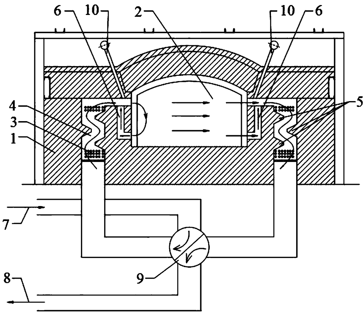
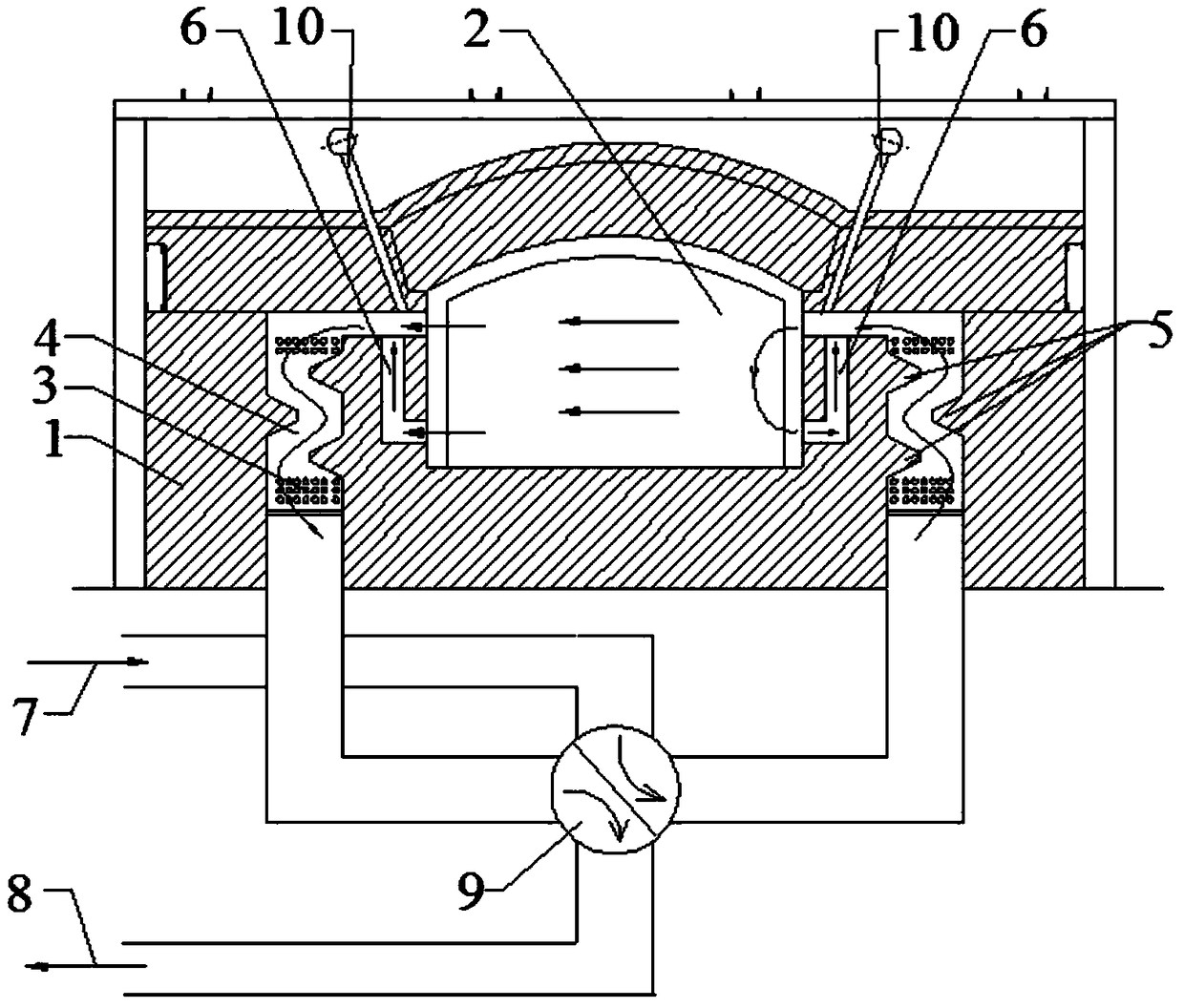
[0021] Such as figure 1 , 2 As shown in 6-8, a regenerative heating furnace with gas circulation pipelines includes a furnace body 1, a furnace chamber 2, a furnace door, and a furnace door sealing structure. The furnace body 1 is provided with a pair of heat storage chambers 4 With a pair of gas circulation pipes 6, the gas circulation pipe 6 is inside and the heat storage tank 4 is outside. One end of the gas circulation pipe 6 communicates with the heat storage compartment 4, and the other end communicates with the lower part of the furnace 2. The inner wall of the heat storage compartment 4 is from above A barrier device 5 is arranged in the lower interval, and the heat storage compartment 4 is filled with a heat storage 3.

[0022] The furnace door sealing structure is arranged at the furnace door of the furnace body 1. The furnace door includes a furnace door cover 12.3 and a heat-resistant filler layer 12.2 located inside the furnace door cover 12.3. The heating furnace inc...

Embodiment 2

[0025] Such as Figure 1-3 As shown in 6-8, a regenerative heating furnace with gas circulation pipelines includes a furnace body 1, a furnace chamber 2, a furnace door, and a furnace door sealing structure. The furnace body 1 is provided with a pair of heat storage chambers 4 With a pair of gas circulation pipes 6, the gas circulation pipe 6 is inside and the heat storage tank 4 is outside. One end of the gas circulation pipe 6 communicates with the heat storage compartment 4, and the other end communicates with the lower part of the furnace 2. The inner wall of the heat storage compartment 4 is from above A barrier device 5 is arranged in the lower interval, and the heat storage compartment 4 is filled with a heat storage 3.

[0026] The furnace door sealing structure is arranged at the furnace door of the furnace body 1. The furnace door includes a furnace door cover 12.3 and a heat-resistant filler layer 12.2 located inside the furnace door cover 12.3. The heating furnace incl...

Embodiment 3

[0029] Such as Figure 1-8 As shown, a regenerative heating furnace with a gas circulation pipeline includes a furnace body 1, a furnace chamber 2, a furnace door, and a furnace door sealing structure. The furnace body 1 is provided with a pair of heat storage chambers 4 and a pair of gas Circulation pipe 6, gas circulation pipe 6 is inside, heat storage compartment 4 is outside. One end of gas circulation pipe 6 communicates with heat storage compartment 4, and the other end communicates with the lower part of furnace 2, and the inner wall of heat storage compartment 4 is spaced from top to bottom. There is a barrier device 5, and the heat storage chamber 4 is filled with a heat storage 3.

[0030] The furnace door includes a furnace door support frame 11.1, heat-resistant bricks 11.2, a limit device 11.3, a tie rod 11.4, a gas cabin 11.5, a connecting block 11.6, a bracket 11.8 and a connecting groove 11.9, the cylinder body of the gas cabin 11.5, and a bracket 11.8 One end of...


PUM


Abstract

The invention relates to a regenerative heating furnace with gas turnover pipelines. The regenerative heating furnace comprises a furnace body, a furnace door and a hearth. A pair of heat-storage cabins and the pair of gas turnover pipelines are arranged in the furnace body, the gas turnover pipelines are close to the interior, and the heat-storage cabins are close to the exterior. One end of eachgas turnover pipeline communicates with the corresponding heat-storage cabin, and the other end of each gas turnover pipeline communicates with the lower portion of the hearth. Blocking devices are arranged on the inner walls of the heat-storage cabins at intervals from top to bottom. The heat-storage cabins are filled with heat-storage devices. The gas turnover pipelines are arranged in the furnace body of the heating furnace, one end of each gas turnover pipeline communicates with the corresponding heat-storage cabin, and the other end of each gas turnover pipeline communicates with the lower portion of the hearth. The connecting position of the gas turnover pipeline on the left side and the corresponding heat-storage cabin forms the negative pressure, a cycle of smoke exists in the gasturnover pipelines, and the high-temperature smoke on the upper portion of the hearth downwards moves, so that a workpiece is evenly heated.

Description

Technical field [0001] The invention relates to the technical field of heating furnace equipment, in particular to a regenerative heating furnace with a gas circulation pipeline. Background technique [0002] In the metallurgical industry, heating furnaces are equipment (industrial furnaces) that heat materials or workpieces (usually metals) to the rolling temperature for forging. Heating furnaces are used in many industries such as petroleum, chemical industry, metallurgy, machinery, heat treatment, surface treatment, building materials, electronics, materials, light industry, daily chemicals, and pharmaceuticals. [0003] The existing heating furnace has the following problems: 1) The flue gas channel of the existing regenerative heating furnace is in the upper part of the furnace. Since there is no gas circulation pipe, the temperature of the workpiece in the upper part of the furnace is high when the workpiece is heated in the furnace. The temperature of the workpiece in the l...

Claims


Application Information

Patent Timeline
Patent Type & Authority Applications(China)
IPC IPC(8): F27B17/00F27D17/00F27D1/18
CPCF27B17/0016F27D1/1858F27D17/004F27D2017/007
Inventor 刘畅
Owner 刘畅
Why Eureka
Try Eureka