
Signal lightning protector with remote signaling function

A technology of signal lightning protection and function, which is applied in the direction of automatic disconnection emergency protection device, emergency protection circuit device for limiting overcurrent/overvoltage, electrical components, etc., and can solve the problem that signal lightning protection device does not have remote signal output Function and other issues, to achieve the effect of simple structure, reliable signal output, and reduce the possibility of lightning damage

Active Publication Date: 2013-06-05
SHENZHEN COMPTON TECH +2
View PDF2 Cites 0 Cited by
  • Summary
  • Abstract
  • Description
  • Claims
  • Application Information

AI Technical Summary

Problems solved by technology

[0003] The invention provides a signal lightning protector with remote signaling function, which can effectively suppress the induced lightning introduced by the communication line, and solves the problem that most of the existing signal lightning protectors do not have the function of remote signaling output

Method used


Image

  • Signal lightning protector with remote signaling function
  • Signal lightning protector with remote signaling function
  • Signal lightning protector with remote signaling function

Examples


Embodiment 1

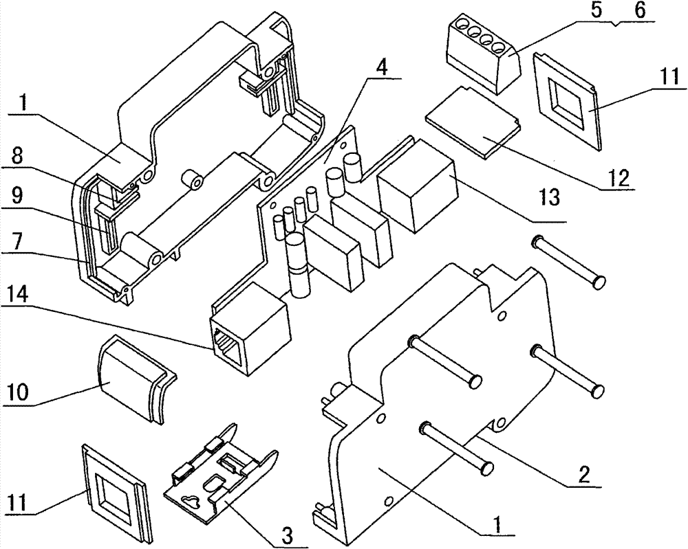
[0012] In this embodiment, the Ethernet signal SPD product is taken as an example, from figure 1 It can be seen that the present invention includes a housing 1 and a PCB lightning protection circuit board 4. The housing 1 is divided into left and right parts, which are connected by bolts. The lower part of the housing 1 is provided with an integrated guide rail 2 and an installation card 3. The PCB lightning protection circuit board 4. It is fixed in the housing 1 by screws; the rear-stage lightning protection device TVS transient suppression diode of the lightning protection line and the low-temperature fuse are packaged in parallel in a plastic case cured by epoxy resin to form a signal lightning protection module, and the low-temperature fuse Both ends are connected to remote signal data terminal 5, so that the heat released when the lightning protection device deteriorates is transferred to the low-temperature fuse as much as possible. When the device deteriorates, when the...

Embodiment 2

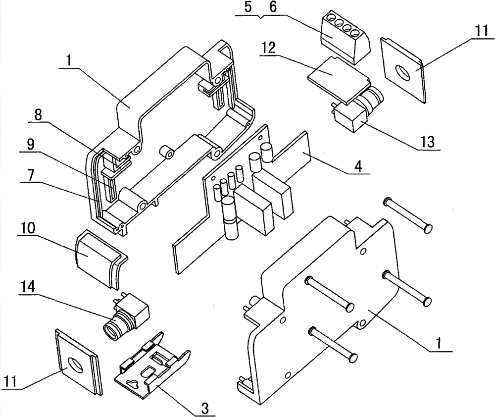
[0014] This embodiment takes the 2M data (L9) signal lightning arrester product as an example, by figure 2 It can be seen that, different from Embodiment 1, the protection line input interface 13 and the line output interface 14 are 2M data (L9) signal input and output interfaces, and the PCB lightning protection circuit board 4 is a corresponding lightning protection circuit board.

Embodiment 3

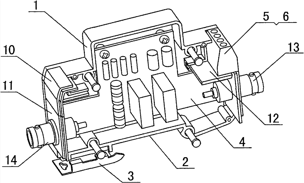
[0016] This embodiment takes the video (BNC) signal lightning arrester product as an example, by image 3 It can be seen that the difference between this embodiment and Embodiment 1 is that the line input interface 13 and the line output interface 14 are video (BNC) signal input and output interfaces respectively, and the PCB lightning protection circuit board 4 is a matching lightning protection circuit board.


PUM


Abstract

The invention relates to the technical field of lightning protecting equipment, in particular to a signal lightning protector with a remote signaling function. Most of the traditional signal lightning protectors have no degraded device remote signaling output function. The products with the remote signaling output function mainly comprise gas discharge tubes and copper pieces which are soldered at low temperature but this is not a reliable way. The technical scheme of the invention is that a transient voltage suppressor TVS of a backward stage lightning protecting apparatus of a lightning protecting line and a low temperature fuse are encapsulated in parallel to form a signal lightning protecting module and remote signaling data terminals are connected at both ends of the low temperature fuse. The remote signaling data terminals, a lightning protecting earth point PE, a line input interface or a signal input terminal and a line input interface or a signal output terminal are mounted on the shell. The invention has a simple structure, realizes the combined design of different protecting interfaces and has reliable remote signaling dry contact signal output so that the maintenance personnel can monitor the work state of the lightning protector in real time remotely.

Description

technical field [0001] The invention relates to the technical field of lightning protection equipment, in particular to a signal lightning protection device with remote signaling function. Background technique [0002] The signal lightning arrester is mainly used in the protection of the induced lightning current in the communication line, and is connected in series between the protected equipment and the signal channel to protect the equipment from being damaged by lightning. At present, most of the signal SPDs on the domestic market do not have the remote signal output function of device degradation, and maintenance personnel cannot remotely monitor the working status of the SPD in real time. Some products with remote signal terminal output use gas discharge tubes in their internal structures. Composed with copper parts through low-temperature solder, the temperature of the gas discharge tube when it fails melts the solder, and the copper parts are separated to generate an...

Claims


Application Information

Patent Timeline
Patent Type & Authority Patents(China)
IPC IPC(8): H02H9/04H02H5/04
Inventor 吴波崔利俊雷全学谷文旗张雁忠贾广明刘伟段振坤张忠民张广辉林雄武
Owner SHENZHEN COMPTON TECH
Learn More