Motor activation circuit for a rail vehicle and method for the operation thereof

A control circuit and rail vehicle technology, applied in the direction of railway vehicles, vehicle components, control/regulation systems, etc., can solve the problem of not being able to fully utilize the efficiency of the engine control circuit, and achieve the effect of simplifying the engine control circuit

Inactive Publication Date: 2011-01-26
SIEMENS AG
View PDF6 Cites 6 Cited by
  • Summary
  • Abstract
  • Description
  • Claims
  • Application Information

AI Technical Summary

Problems solved by technology

However, this selection of the rated intermediate circuit DC voltage ultimately leads to the fact that the efficiency of the motor control circuit cannot be fully utilized both on the input side and on the output side.

Method used


Image

  • Motor activation circuit for a rail vehicle and method for the operation thereof
  • Motor activation circuit for a rail vehicle and method for the operation thereof
  • Motor activation circuit for a rail vehicle and method for the operation thereof

Examples


Embodiment Construction

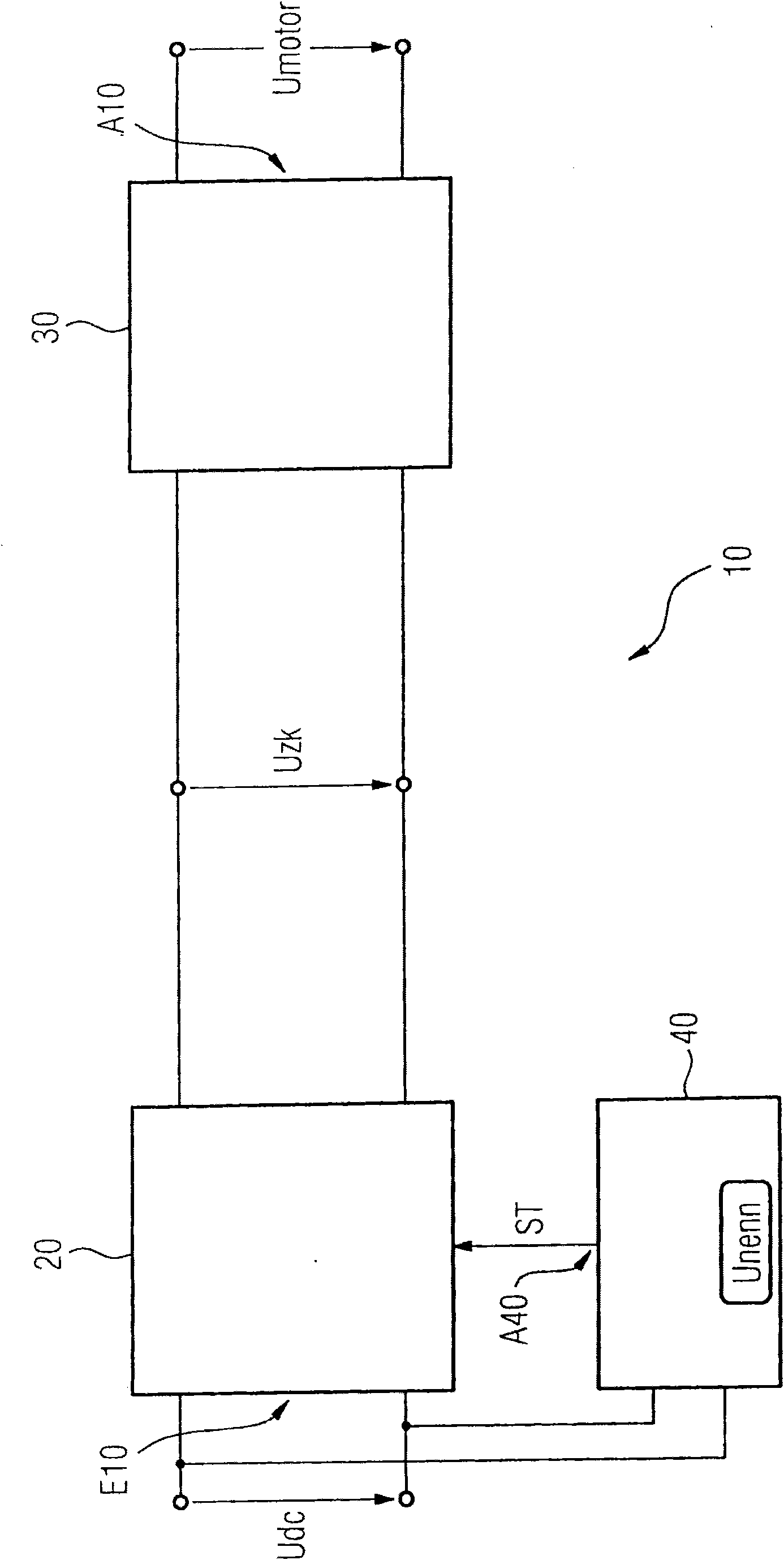
[0028] exist image 3 It can be seen in the figure that the engine control circuit 10 is applied with the mains DC voltage Udc at its input E10. On the output side, motor control circuit 10 generates a motor drive voltage at output A10 , which is denoted by the reference Umotor and can be, for example, a three-phase voltage.

[0029] On the input side, the motor control circuit 10 has a step-up converter 20 , after which a pulse-modulated inverter 30 is connected. The step-up converter 20 is actuated by a control device 40 in which a setpoint intermediate circuit DC voltage Unenn is predefined either fixedly or within certain limits.

[0030] The control device 40 is connected on the input side indirectly or directly to the input E10 of the engine control circuit 10 , so that the mains DC voltage Udc or a measured value corresponding to the mains DC voltage Udc can also be supplied to the control device 40 .

[0031]At the output A40, the control device 40 generates a contro...


PUM


Abstract

The invention relates to a motor activation circuit (10) for a rail vehicle having a boost converter, which is disposed at the input of the motor activation circuit, and which converts a mains DC voltage (Udc), which is applied at the input of the motor activation circuit, into an intermediate circuit DC voltage (Uzk), a pulse rectifier, which is downstream from the boost converter, and which can be connected at the output to a drive motor of the rail vehicle and is capable of converting the intermediate circuit DC voltage of the boost converter into a motor drive voltage for driving the drive motor, and a control unit, which activates the boost converter and which activates the boost converter in operation such that said converter generates the predetermined rated intermediate circuit DC voltage for a mains DC voltage below a predetermined rated intermediate circuit DC voltage as the intermediate circuit DC voltage. According to the invention, the control unit is designed such that it activates the boost converter (20) for a mains DC voltage (Udc) above the rated intermediate circuit DC voltage (Unenn) such that said converter generates an intermediate circuit DC voltage (Uzk) identical to the mains DC voltage (Udc) or an intermediate circuit DC voltage, which is greater at most by a predetermined offset value (Uoffset), and feeds said intermediate circuit DC voltage into the pulse rectifier.

Description

technical field [0001] The invention relates to an engine control circuit for rail vehicles with a boost converter arranged at the input of the engine control circuit, a pulse-modulated inverter connected downstream of the boost converter, and Control unit for controlling the step-up converter, which converts the grid DC voltage applied at the engine control circuit on the input side into an intermediate circuit DC voltage, the pulse-modulated inverter being switchable on the output side A transmission engine of a rail vehicle and is suitable for converting the intermediate circuit DC voltage of a boost converter into a motor drive voltage for driving the transmission engine, the control device controlling the boost converter in operation such that the boost converter The voltage converter generates a predetermined rated intermediate circuit direct voltage as an intermediate circuit direct voltage for a system DC voltage which is lower than a predetermined rated intermediate c...

Claims


Application Information

Patent Timeline
Patent Type & Authority Applications(China)
IPC IPC(8): B60L9/30H02M1/10H02M3/142
CPCB60L2200/26H02M3/1582H02M2001/007B60L9/30H02M7/53871H02M3/1584B60L2210/14Y02T10/7225H02M1/007Y02T10/72
Inventor 赫伯特·甘巴赫马丁·格林加乌尔里克·温克曼
Owner SIEMENS AG
Why Eureka
Try Eureka