
Device for testing the coating of a vane base

A detection device and coating technology, which is applied in the field of coating devices, can solve the problems of unacceptable coating quality differences, insufficient accurate conclusions on durability and mechanical properties, etc., and achieve good representative results

Active Publication Date: 2013-06-05
SN DETUDE & DE CONSTR DE MOTEURS DAVIATION S N E C M A
View PDF5 Cites 0 Cited by
  • Summary
  • Abstract
  • Description
  • Claims
  • Application Information

AI Technical Summary

Problems solved by technology

[0004] However, it is clear that various tests have proven useful for distinguishing high-quality coatings from coatings of only acceptable quality, and for forming precise conclusions related to the in-service durability and mechanical properties of coatings deposited on blade roots. saying is not enough
[0005] If the cycle of the blade (or blade root) is used to indicate the set of stresses that the blade is subjected to during the operational phase (while the aircraft equipped with the turboreactor is in flight), i.e. from start to stop, the foregoing means , as long as the blade can be subjected to multiple cycles in a satisfactory manner, the current test does not allow to express quality differences between different coatings

Method used


Image

  • Device for testing the coating of a vane base
  • Device for testing the coating of a vane base

Examples


Embodiment Construction

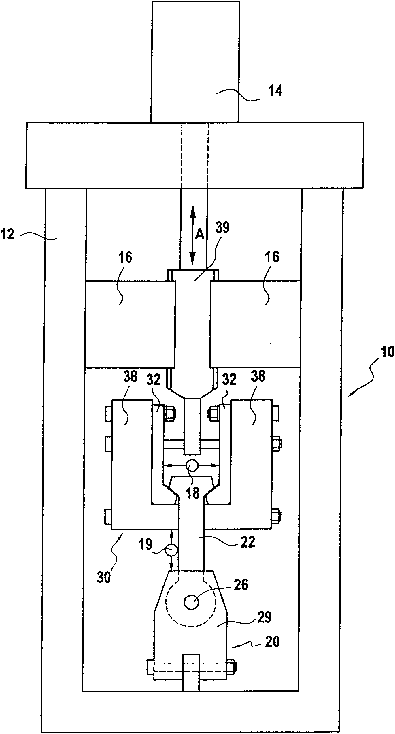
[0032] see figure 1 , a detection device 10 according to the invention for a coating that can be applied to a blade root is now described. This device 10 comprises a machine comprising first of all a frame 12 constituted in its entirety by a mechanically welded frame. This framework 12 supports two retention systems 20 and 30 .

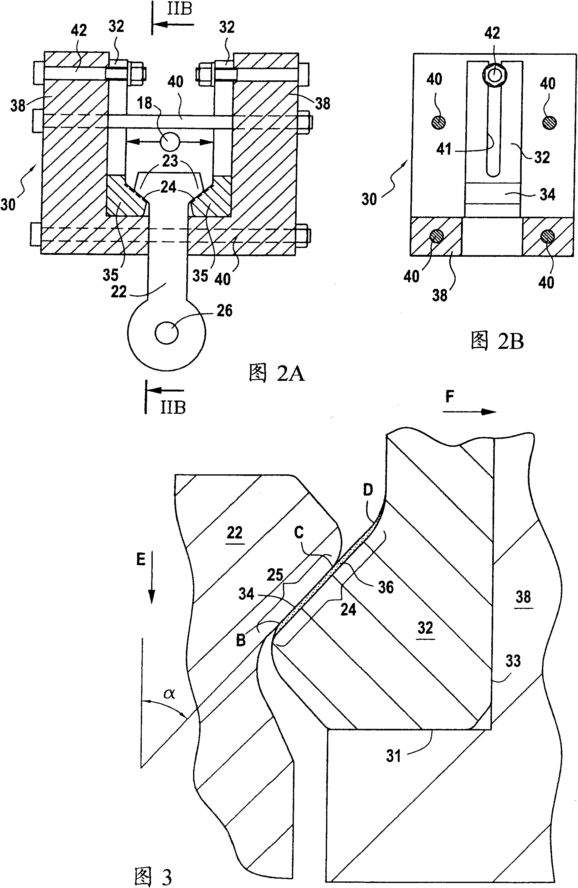
[0033] A first holding system 20 located in the lower part of the machine comprises fixed struts 29 holding the counter detection 22 in position. The counter-test 22 comprises a hole through which a mandrel 26 of the first holding system passes, with which the counter-test 22 is held regardless of the tensile stress it is subjected to.

[0034] A second holding system 30 is used to hold the two detection halves 32 in position. This second holding system 30 comprises a movable beam 39 arranged to be translated alternately along the double arrow A in the vertical direction by the linear actuator 14 or any other equivalent actuation mechanism. This b...


PUM


Abstract

A device for testing a coating for a turbomachine rotor disk blade root, including two test piece halves, each including a bearing surface coated with the coating, one counter test piece including two bearing surfaces, and a machine including a first holding system for the counter test piece and a second holding system for holding the test piece halves around the counter test piece. With a tensile mechanism, the holding systems are subjected to predetermined tensile cycles along the tensile axis, during which the tensile force is transmitted from one holding system to the other via the respective bearing surfaces contacting the counter test piece and the test piece halves. The second holding system includes a resilient return mechanism allowing for the two test piece halves to open up in a direction perpendicular to the tensile direction.

Description

technical field [0001] The invention relates to the field of wear-resistant coatings applied to the roots of rotating machine blades and their quality control. More precisely, the invention relates to a device for detecting a coating capable of coating the root of a turbine rotor blade. This could be a land or aviation turbine, i.e. an aircraft turbine reactor or a turboprop. Background technique [0002] Blades, especially fan blades in aerospace turbines, are extremely stressed mechanical components. For this reason, the blade root as the blade holding part is a particularly critical part of the component. The blade root includes: the contact surface with the rotor disk, or bearing surface, which is subjected to pressure and high temperature in operation. In order to reduce the stresses, ie shear stresses, applied to the bearing surface of the blade root, wear-resistant coatings are used in a known manner. These so-called wear-resistant coatings can be deposited by the...

Claims


Application Information

Patent Timeline
IPC IPC(8): G01N3/56
CPCG01N3/56
Inventor 艾伦·拜索特劳伦特·都彭安妮-克莱尔·毕廖内
Owner SN DETUDE & DE CONSTR DE MOTEURS DAVIATION S N E C M A
Learn More