Electric dust collector

A vacuum cleaner and electric technology, which is applied in the installation of vacuum cleaners, electrical components, cables, etc., can solve the problems of poor convenience of use and reduced attractiveness of electric vacuum cleaners, and achieve the effect of preventing failures

Inactive Publication Date: 2011-02-02
SANYO ELECTRIC CO LTD +1
View PDF7 Cites 2 Cited by
  • Summary
  • Abstract
  • Description
  • Claims
  • Application Information

AI Technical Summary

Problems solved by technology

[0006] In the electric vacuum cleaner described in Patent Document 1, in order to prevent the dust on the floor from being raised, the user has to tilt the wings one by one, so the usability is poor.
In addition, even if the exhaust port is opened, the wings are arranged opposite to the exhaust port, so the wings become obstacles to the air discharged from the exhaust port, so that the suction force of the electric vacuum cleaner may decrease.

Method used


Image

  • Electric dust collector
  • Electric dust collector
  • Electric dust collector

Examples


Embodiment Construction

[0053] Hereinafter, embodiments of the present invention will be specifically described with reference to the drawings.

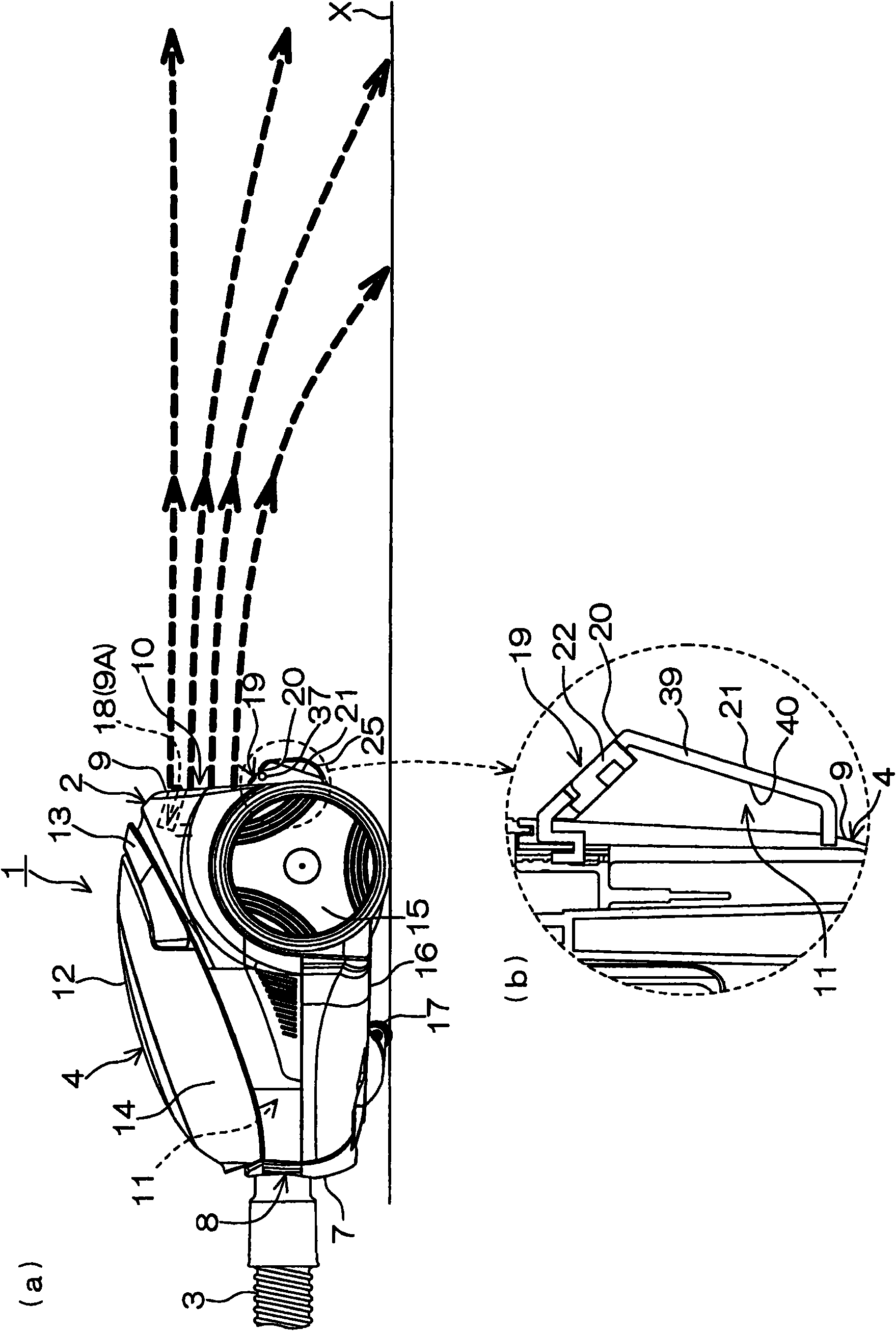
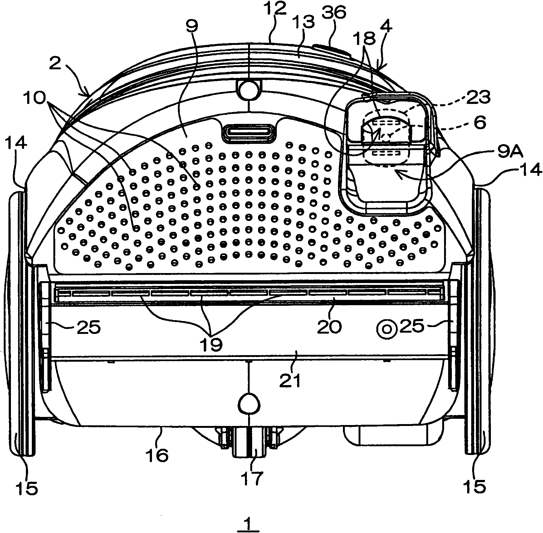
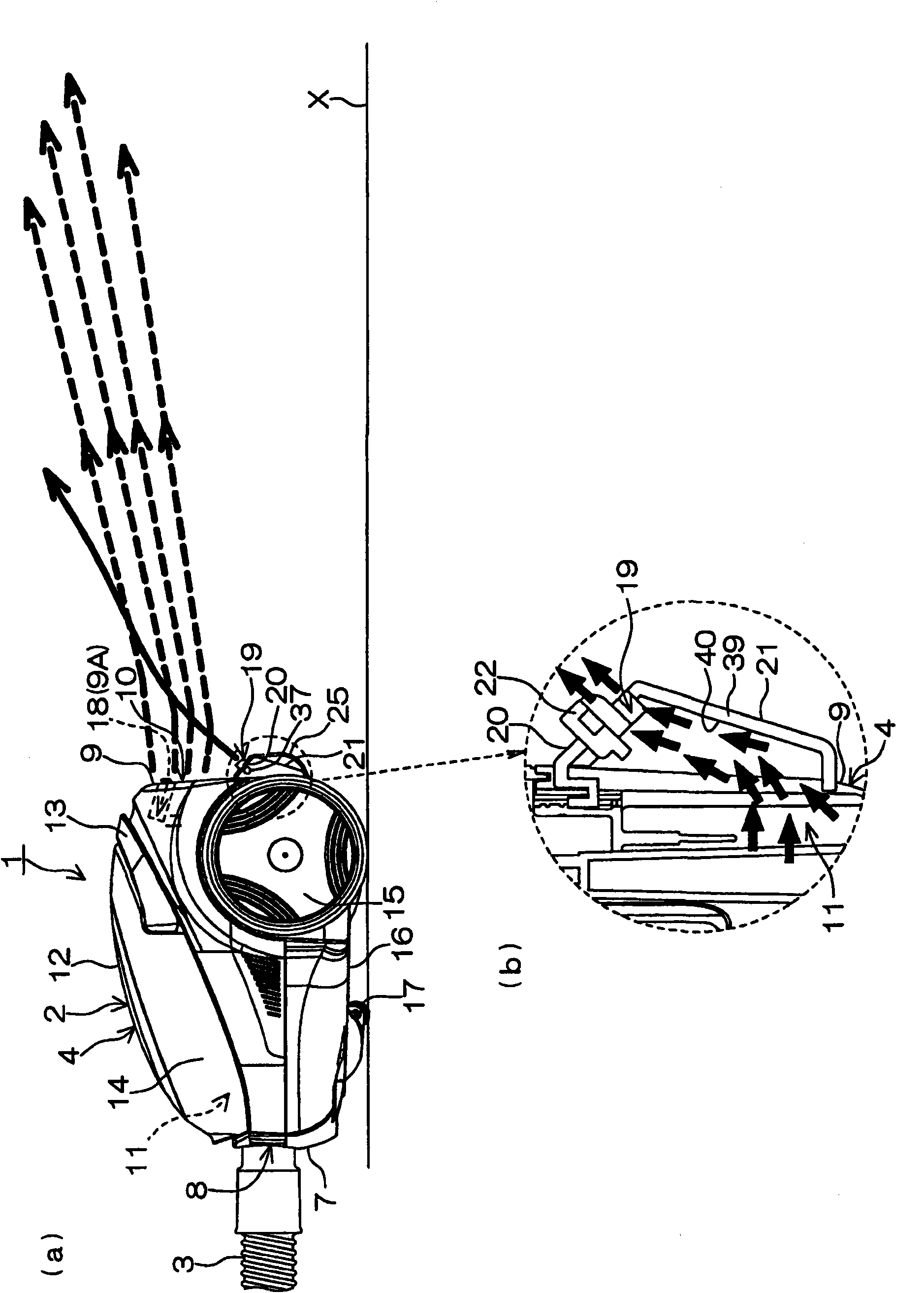
[0054] figure 1 (a) is a right side view of electric vacuum cleaner 1 which concerns on one Embodiment of this invention, (b) is a main part right side cross-sectional view of (a). figure 2It is a rear view of the vacuum cleaner 1 . Hereinafter, as for the description of the electric vacuum cleaner 1 and its structural components, unless otherwise specified in advance, for convenience, the figure 1 In (a), the left side is defined as the front side, the right side is defined as the rear side, the front side is defined as the right side, and the inner side is defined as the left side. In addition, the left-right direction is the same as the width direction.

[0055] Such as figure 1 As shown in (a), the electric vacuum cleaner 1 includes a vacuum cleaner body 2 and a hose 3. Although not shown, the front end of the hose 3 includes an operation unit for ...


PUM


Abstract

The invention provides an electric dust collector capable of preventing suction force from reducing and meanwhile increasing the use convenience, in a structure capable of preventing dust on a floor from being raised. A spray port (19) capable of obliquely spraying air flow upwards is formed on a frame of an electric dust collector (1) below an exhaust port (10). The air flow collides with an exhaust flow from the exhaust port (10) to make the air from the frame (4) flowing upwards to apart from the floor surface (X), so as to prevent the dust on the floor from raising due to exhaust. Because the exhaust port (10) is always opened, the air is smoothly exhausted from the exhaust port (10) to prevent the suction force from being reduced. If an electric blower (5) is driven, the air flow automatically sprays from the spray port (19) to collide with the exhaust flow from the exhaust port (10), thus the dust on the floor is cushily prevented from being raised.

Description

technical field [0001] The invention relates to an electric vacuum cleaner. Background technique [0002] An electric vacuum cleaner employing a mechanism for preventing dust on the floor from being blown up by air discharged from an exhaust port of the cleaner body is known (see Patent Document 1). [0003] In the electric vacuum cleaner described in Patent Document 1, the wings are attached to the lower part of the exhaust port of the vacuum cleaner main body via hinges. The wing closes the air outlet when the electric vacuum cleaner is not in use, but can be rotated around the hinge to tilt at any angle to open the air outlet. [0004] In order to use the electric vacuum cleaner, tilt the wings to an appropriate angle in advance to open the exhaust port, and then turn on the switch of the electric vacuum cleaner. At this time, the air in the main body of the vacuum cleaner is guided by the inclined wings and discharged upward from the exhaust port. Therefore, it is poss...

Claims


Application Information

Patent Timeline
Patent Type & Authority Applications(China)
IPC IPC(8): A47L9/00A47L9/26
Inventor 上垣内茂森田明宏土田英也武中和彦水岛祐之辅
Owner SANYO ELECTRIC CO LTD
Why Eureka
Try Eureka