

Chemical pump filter device
A filter device and chemical pump technology, applied in the direction of filtration separation, gravity filter, chemical instruments and methods, etc., can solve the problems of affecting work efficiency, clogging the impeller flow channel, reducing the pump outlet pressure, etc., so as to improve the integrity rate and protect the Effect of sealing and prolonging service life
Inactive Publication Date: 2011-02-02
JIANGSU LINGFEI CHEM
View PDF0 Cites 3 Cited by
- Summary
- Abstract
- Description
- Claims
- Application Information
AI Technical Summary
Problems solved by technology
When the liquid contains a large amount of solid impurities, these impurities will continue to hit the impeller, which will gradually damage the surface of the impeller, affect the working efficiency, and even block the flow path of the impeller in serious cases, greatly reducing the outlet pressure of the pump; affect the seal of the pump, causing the pump to leak
Method used
View moreImage
Smart ImageViewing Examples

Examples
Embodiment Construction
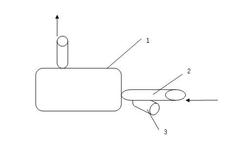
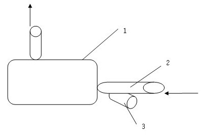
[0009] Such as figure 1 As shown, a filter device for a chemical pump includes a pump body 1 and an inlet pipe 2, the inlet pipe 2 is connected to the inlet of the pump body 1, and is characterized in that a filter is provided on the inlet pipe 2. The filter is a filter bag 3, which is installed below the inlet pipe 2 through an interface, and one end of the filter bag 3 extends into the inlet pipe, intercepts in the inlet pipe 2, and filters out impurities. The interface of the filter bag 3 is fixed with screws, which is convenient for cleaning the filter bag after disassembly.
Login to View More PUM
 Abstract
The invention discloses a chemical pump filter device, which comprises a pump body and an inlet pipeline, wherein the inlet pipeline is connected on the inlet of the pump body, and a filter is arranged on the inlet pipeline. The filter is a filter bag, the filter bag is arranged below the inlet pipeline through an interface, and one end of the filter bag extends into the inlet pipeline. The filter with the simple structure in the device can effectively filter impurities in liquid so that the impurities do not enter the chemical pump, the service life of an impeller is prolonged, the seal is protected and the perfectness rate of the chemical pump is improved.
Description
[0001] technical field [0002] The invention relates to a chemical reactor, in particular to a chemical pump filter device. Background technique [0003] Chemical pump is a kind of liquid material conveying equipment widely used in chemical industry, mainly centrifugal pump, which is suitable for pumping corrosive liquid in the container. Its working principle is: before the pump is turned on, the suction pipe and the pump must be filled with liquid. After the pump is turned on, the impeller rotates at a high speed, and the liquid in it rotates with the blades. Under the action of centrifugal force, it flies away from the impeller and shoots out. The speed of the liquid in the diffusion chamber of the pump casing gradually slows down, the pressure gradually increases, and then flows out from the pump outlet and the discharge pipe. At this time, a vacuum low-pressure area without air and liquid is formed at the center of the blade due to the liquid being thrown to the surro...
Claims
Login to View More Application Information
Patent Timeline
 IPC IPC(8): B01D35/02B01D29/27
Inventor钱飞
OwnerJIANGSU LINGFEI CHEM