Fuel battery pile

A fuel cell stack and electrolyte technology, applied to fuel cell components, solid electrolyte fuel cells, battery pack components, etc., can solve problems such as poor supply of oxidant gas, decline in fuel cell output performance, and blockage of connecting flow paths. Achieve simple structure, prevent clogging, and suppress dimensional changes

Active Publication Date: 2011-02-02
HONDA MOTOR CO LTD
View PDF3 Cites 8 Cited by
  • Summary
  • Abstract
  • Description
  • Claims
  • Application Information

AI Technical Summary

Problems solved by technology

However, there is a possibility that the connecting flow paths 6a and 6b may be blocked due to deformation of the rubber bridge due to fluctuations in the load of the seal or aging of the rubber.
Therefore, there is a problem that the supply of oxidizing gas and the like is poor and the output performance of the fuel cell is lowered.

Method used


Image

  • Fuel battery pile
  • Fuel battery pile
  • Fuel battery pile

Examples


Embodiment Construction

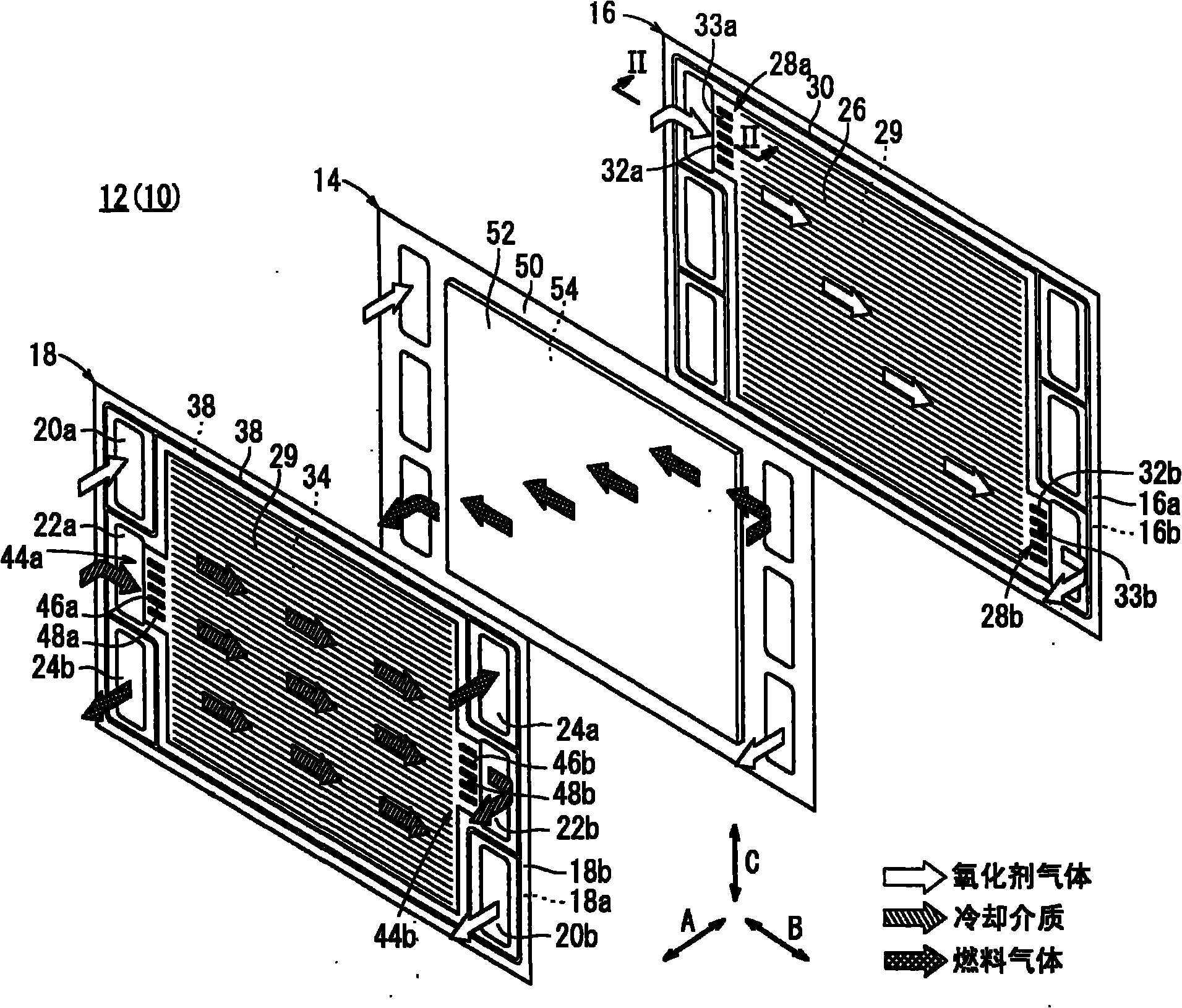
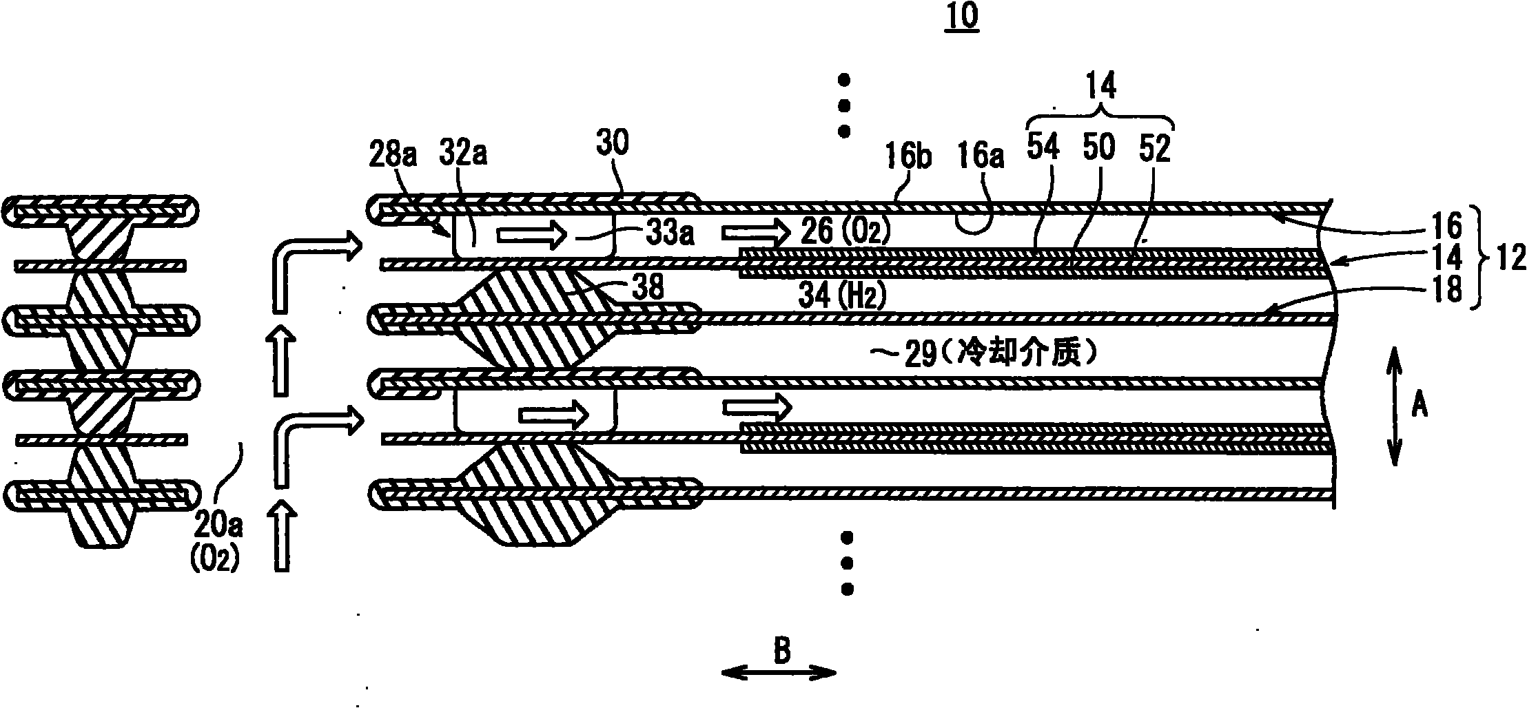
[0058] Such as figure 1 and figure 2 As shown, the fuel cell stack 10 according to the first embodiment of the present invention is formed by stacking a plurality of fuel cells 12 in the horizontal direction (direction of arrow A) or vertical direction (direction of arrow C).

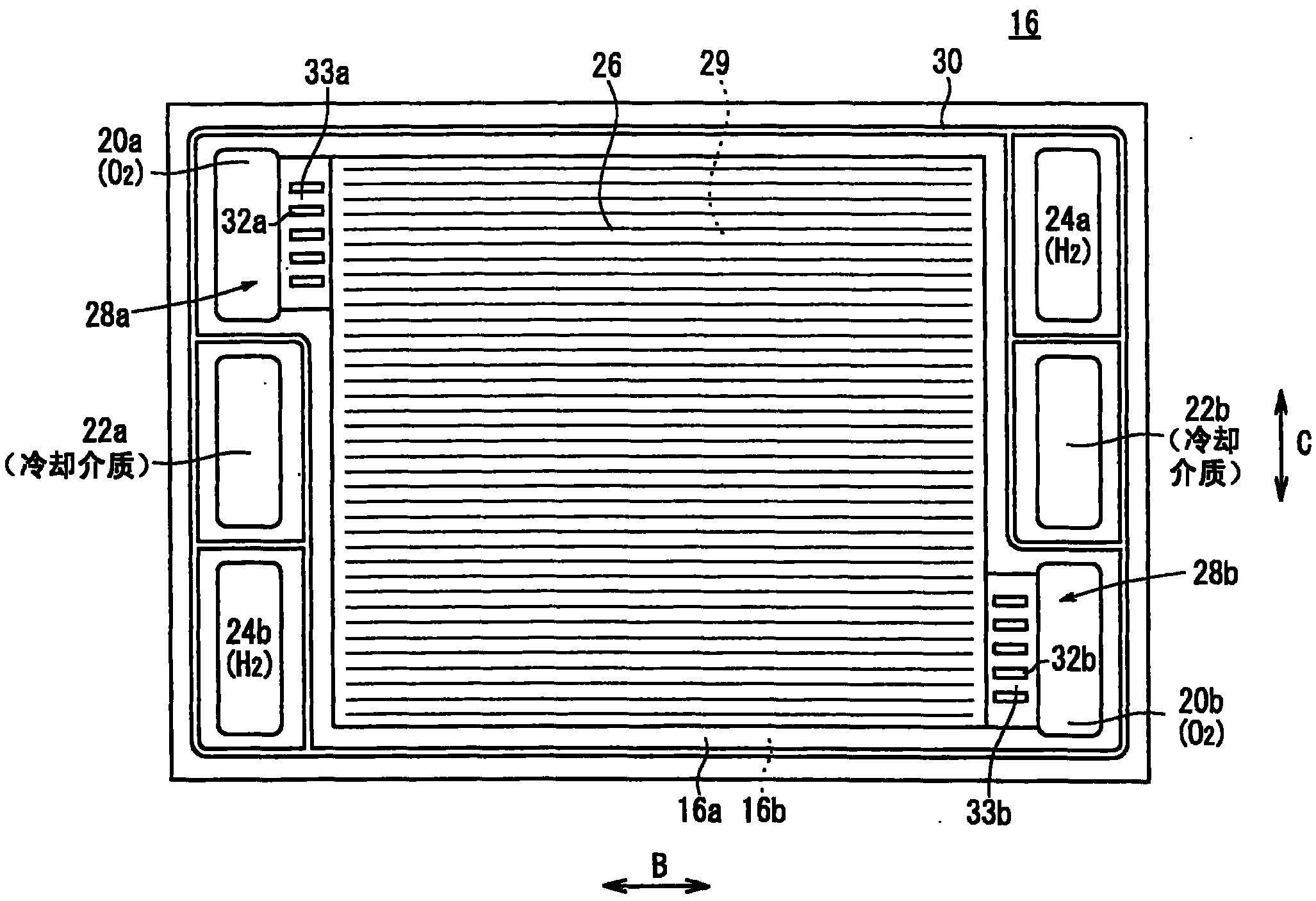
[0059] In the fuel cell 12 , an electrolyte membrane-electrode structure (electrolyte-electrode structure) 14 is sandwiched between first metal separators 16 and second metal separators 18 . The first metal separator 16 and the second metal separator 18 are made of, for example, a steel plate, a stainless steel plate, an aluminum plate, or a plated steel plate, and are punched into a corrugated plate shape to form a flow path described later.

[0060] Such as figure 1 As shown, in the arrow B direction of the fuel cell 12 ( figure 1 , in the horizontal direction) along the arrow C direction (vertical direction) along the arrow C direction (vertical direction) arranged in a stacking direction, that ...


PUM


Abstract

The invention provides a fuel battery pile capable of preventing a flow path from being blocked due to destruction of a connection bridge part as much as possible in an economic and simple structure. In the fuel battery (12) for forming the fuel battery pile (10), an electrolyte film-electrode structure (14) is clamped by a first metal separator (16) and a second metal separator (18). The connection bridge part (28a) for communicating an oxidant gas flow path (26) with an oxidant gas inlet communication hole (20a) is arranged on the first metal separator (16) and comprises a plurality of resin passage parts (32a) which are mutually separated and alternatively arranged and a passage (33a) is formed between the resin passage parts (32a).

Description

technical field [0001] The present invention relates to a fuel cell stack in which an electrolyte-electrode structure having a pair of electrodes arranged on both sides of an electrolyte and a metal separator are laminated, and a fluid flow path and a fluid communication hole are formed, wherein the The fluid channel allows fluid to flow in the plane direction of the metal separator, and the fluid is at least any one of fuel gas, oxidant gas, or cooling medium, and the fluid communication holes supply the fluid along the lamination direction. Background technique [0002] For example, a solid polymer fuel cell includes a unit cell in which an electrolyte membrane-electrode assembly (MEA) is sandwiched between a pair of separators between electrolyte membranes formed of polymer ion exchange membranes. An anode-side electrode and a cathode-side electrode are arranged on both sides, respectively. Such a fuel cell is generally used as a fuel cell stack by stacking a predetermin...

Claims


Application Information

Patent Timeline
Patent Type & Authority Applications(China)
IPC IPC(8): H01M8/10H01M8/02H01M2/14
CPCY02E60/521Y02E60/50
Inventor 小此木泰介安藤敬祐杉田成利后藤修平田中广行
Owner HONDA MOTOR CO LTD
Why Eureka
Try Eureka