
Non-contact driving method used for faraday cup in accelerator

A non-contact drive, Faraday cylinder technology, applied in the directions of generators/motors, electrical components, etc., can solve problems such as air leakage, vacuum deterioration, metal fatigue of bellows, etc., and achieve the effect of preventing decoupling

Inactive Publication Date: 2011-02-02
CHINA INSTITUTE OF ATOMIC ENERGY
View PDF5 Cites 5 Cited by
  • Summary
  • Abstract
  • Description
  • Claims
  • Application Information

AI Technical Summary

Problems solved by technology

[0002] In the field of accelerators, the path of beam transmission is generally in high vacuum. According to different application requirements, there are many moving devices in the vacuum system, such as Faraday cylinders for beam current measurement, apertures for beam limitation, and Quartz targets or fluorescent targets for beam spot observation, material targets for physical experiments, etc., there are generally two ways to drive these devices in the world: the first is the dynamic sealing method, which relies on pressure to seal the rubber ring and the sliding rod, This method is prone to air leakage when the slider moves, making the vacuum instantly worse
The second is to rely on welded bellows to stretch and compress to seal. This method is currently the most common method in the world. There will be no air leakage during the moving process of the parts. It is suitable for equipment with high vacuum and frequent operations. The disadvantage is that The moving stroke of the components is relatively short, and frequent movements can easily cause metal fatigue of the bellows to cause air leakage
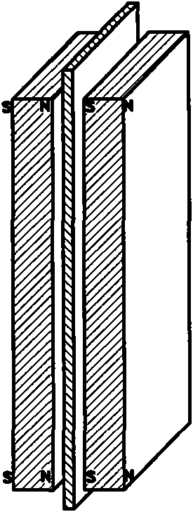
However, the above patent documents and articles disclosed at present all adopt the coupling arrangement between the surfaces of the magnets N and S, such as figure 2 As shown, the N and S poles on both sides of the face-to-face coupling partition are attracted to each other, and the two sides cannot move relative to each other, and friction will occur with the middle partition during the movement process. Therefore, this arrangement cannot quickly realize reciprocating motion, and The surface-to-surface coupling method is prone to decoupling, and cannot achieve the purpose of quickly driving the Faraday cage in the accelerator

Method used

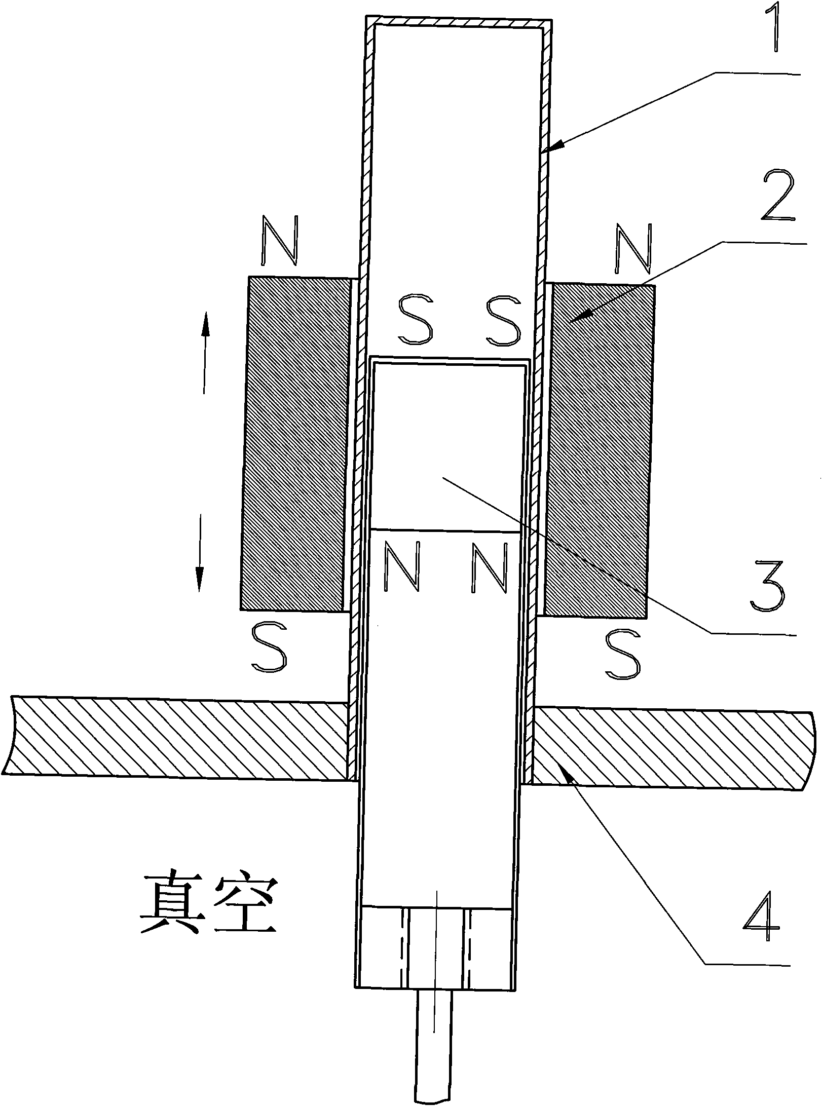

Image

  • Non-contact driving method used for faraday cup in accelerator
  • Non-contact driving method used for faraday cup in accelerator
  • Non-contact driving method used for faraday cup in accelerator

Examples


Embodiment Construction

[0016] The present invention will be further described in detail below in conjunction with the drawings and specific embodiments:

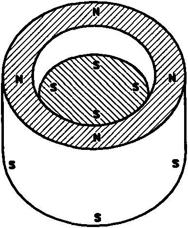
[0017] Such as figure 1 , image 3 , Figure 5 As shown, the non-magnetic metal tube 1 and the housing 4 of the vacuum system are made into an integral structure, wherein the non-magnetic metal tube 1 is made of stainless steel, copper or aluminum and other materials. The cylinder 5 is fixed on the support frame 7, the cylinder shaft 6 is connected with the connecting assembly 8, and the connecting assembly 8 is driven to move up and down, and the magnetic ring 2 is embedded on the connecting assembly 8. The magnetic column 3 is embedded in the upper end of the magnetic column body 9, and the lower end of the magnetic column body 9 is connected to the Faraday tube 10. In this embodiment, a strong magnetic column 3 is connected to a magnetic column body 9, and the magnetic column 3 and the magnetic column body 9 are placed in the non-magnetic metal ...


PUM


Abstract

The invention discloses a non-contact driving method used for a faraday cup in an accelerator, comprising the following steps: a non-magnetic metal tube (1) and a vacuum system shell (4) are manufactured into an integral structure; a magnetic column (3) is embedded at the upper end of a magnetic column body (9); the faraday cup (10) is connected on the magnetic column body (9); the magnetic column (3) is arranged in the non-magnetic metal tube (1) communicated with the vacuum system, and can move smoothly in the metal tube (1); a magnetic ring (2) is sheathed outside the metal tube (1); and the polarity direction of the magnetic ring (2) is opposite to that of the magnetic column; the magnetic column (3) is coupled with the magnetic ring (2). The non-contact driving method provided by the invention is used for the rapid reciprocating motion devices such as faraday cup in the accelerator, and has accurate positioning and rapid driving speed.

Description

Technical field [0001] The invention relates to the technical field of accelerators, in particular to a non-contact driving method for Faraday cylinders in accelerators. Background technique [0002] In the field of accelerators, the transmission path of the beam is generally in high vacuum. According to the needs of different applications, there are many moving devices in the vacuum system, such as the Faraday tube for beam current measurement, the diaphragm for beam limiting, and For the quartz target or fluorescent target for observing the beam spot, the material target for physical experiment, etc., there are generally two methods to drive these devices in the world: the first is the dynamic sealing method, which relies on pressure to seal the rubber ring and the sliding rod. This method is prone to air leakage when the sliding rod moves, which causes the vacuum to deteriorate instantly. The second method is to rely on welded bellows for stretching and compression sealing. T...

Claims


Application Information

Patent Timeline
Patent Type & Authority Applications(China)
IPC IPC(8): H02N11/00
Inventor 苏胜勇杨丙凡
Owner CHINA INSTITUTE OF ATOMIC ENERGY
Learn More