An ear punching machine

A punching machine and lug technology, applied in the direction of punching machines, presses, piercing tools, etc., can solve problems such as punching machines not being realized, battery replacement, and battery modules not being used normally, so as to achieve convenient and fast loading and unloading , high work efficiency, durable effect of the mold

Active Publication Date: 2018-09-18
广东光博智能科技有限公司
View PDF8 Cites 0 Cited by
  • Summary
  • Abstract
  • Description
  • Claims
  • Application Information

AI Technical Summary

Problems solved by technology

[0002] The cells in the existing pouch battery are welded together to form a whole. When one cell in the pouch battery cannot be used normally, a problem arises, that is, the entire cell mold The battery pack cannot be used normally, and the defective battery cell cannot be taken out separately for replacement, only the whole battery cell module can be replaced. It is necessary to improve the existing battery cell structure so that the connection between the battery cell and the battery cell To realize the detachable function, the detachable connection between the battery and the battery needs to punch the tab of the battery, and the punching position of the tab needs to be quite accurate, which cannot be realized by the existing punching machine. Therefore, It is necessary to design a punching machine that can realize the punching of battery tabs

Method used


Image

  • An ear punching machine
  • An ear punching machine
  • An ear punching machine

Examples


Embodiment Construction

[0035] The present invention will be further described below according to the accompanying drawings and specific embodiments, but the embodiments of the present invention are not limited thereto.

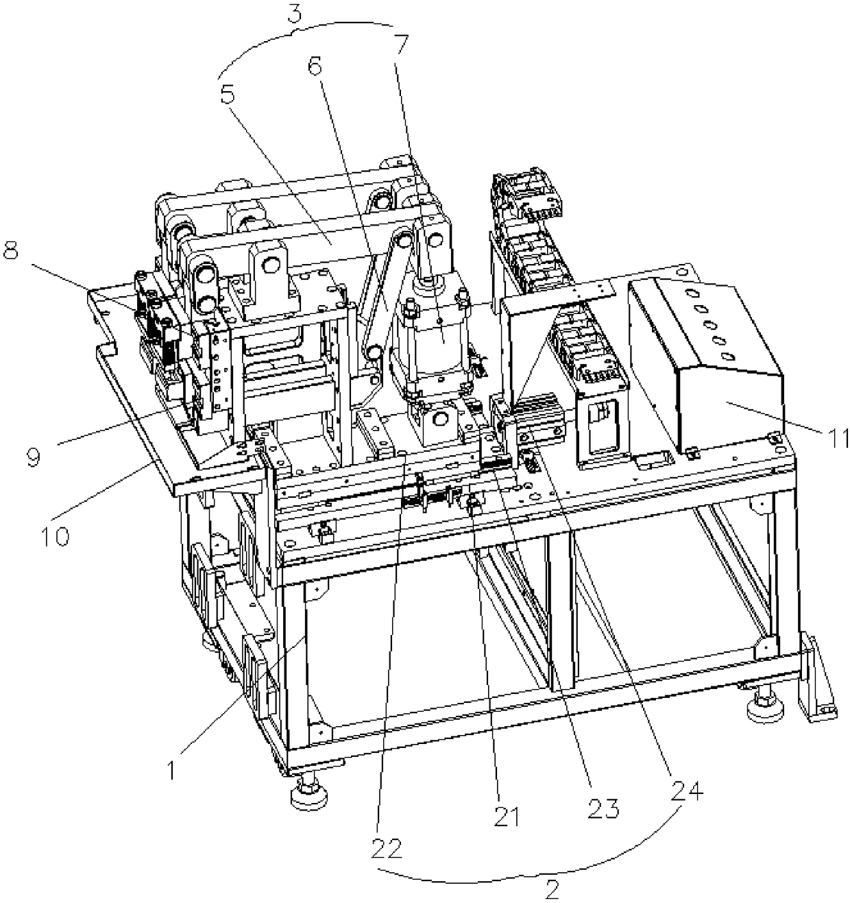
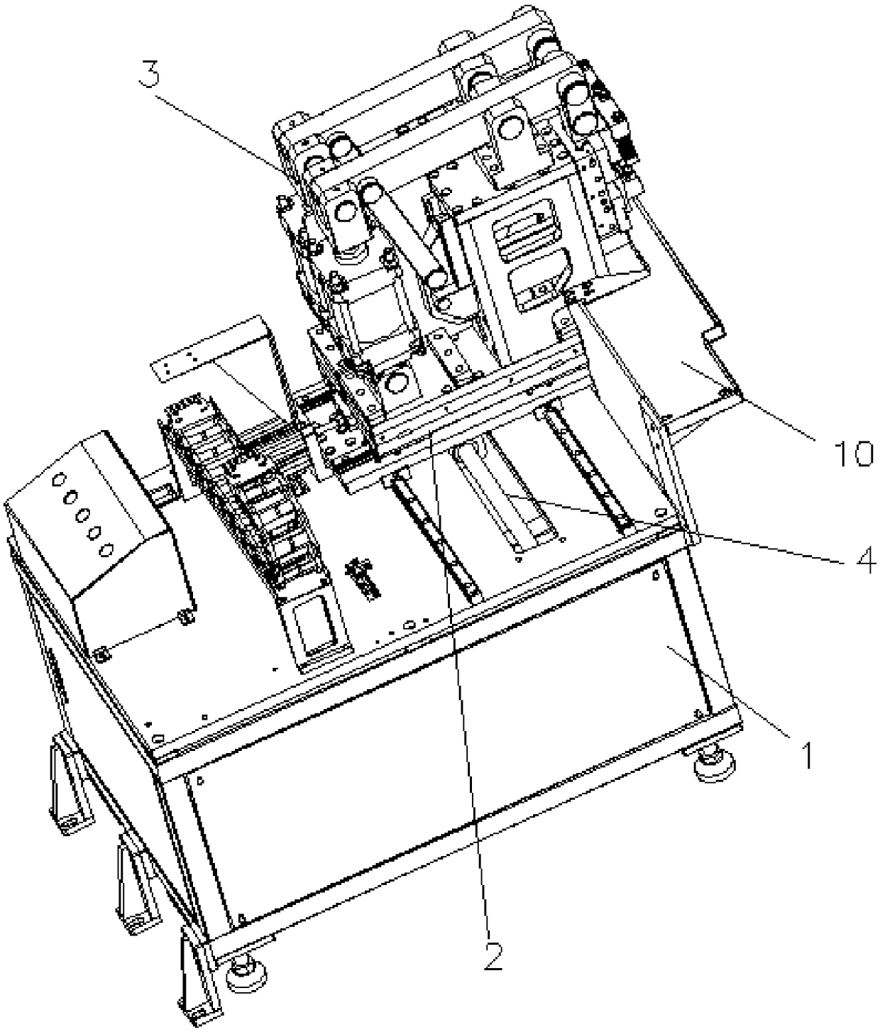
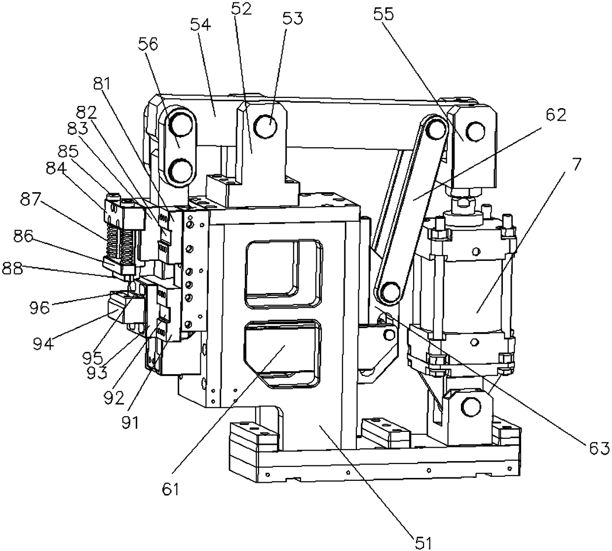
[0036] like figure 1 , figure 2 and image 3 As shown, a tab punching machine includes a frame 1, and the frame 1 is provided with a cylinder propulsion mechanism 2 and at least one set of cylinder connecting rod punching mechanisms 3, and the cylinder propulsion mechanism 2 controls the cylinder connecting rod punching mechanism 3 Left and right movement, the cylinder propulsion mechanism 2 is controlled by the servo motor to move the screw rod 4 back and forth, the cylinder connecting rod punching mechanism 3 includes the upper die connecting rod device 5, the lower die connecting rod device 6 and the jacking cylinder 7, the upper die connecting rod device 5 and the lower mold connecting rod device 6 are controlled by the jacking cylinder 7, when the cylinder connecting rod pun...


PUM


Abstract

The invention discloses a tab punching machine which comprises a rack, wherein an air cylinder feed mechanism and an air cylinder connecting rod punching mechanism are arranged on the rack and move left and right; a screw rod of the air cylinder feed mechanism is controlled by a servo motor to move front and back; the air cylinder connecting rod punching mechanism comprises an upper die connecting rod device, a lower die connecting rod device and a jacking air cylinder; the upper die connecting rod device and the lower die connecting rod device are controlled by the jacking air cylinder; and when the air cylinder connecting rod punching mechanism carries out punching action on a battery cell tab, the upper die connecting rod device controls an upper die to move downwards, and the lower die connecting rod device controls a lower die to move upwards. With adoption of the tab punching machine, four slotted holes are simultaneously punched in the battery cell tab, and two of the slotted holes of the battery cell tab are locked in a tab connecting piece through four screws to overlap battery cells, so that the effect of separately dismantling and replacing the battery cells is realized, and maintenance and reuse are facilitated.

Description

technical field [0001] The invention relates to a battery tab punching device, in particular to a tab punching machine. Background technique [0002] The cells in the existing pouch battery are welded together to make it a whole. When a cell in the pouch battery cannot be used normally, a problem arises, that is, the entire cell mold The battery group cannot be used normally, and the defective battery cell cannot be taken out for replacement alone, only the whole battery cell module can be replaced. It is necessary to improve the existing battery cell structure so that the connection between the battery cell and the battery cell To realize the detachable function, and the detachable connection between the battery and the battery needs to punch the tab of the battery, and the punching position of the tab needs to be quite accurate, which cannot be realized by the existing punching machine. Therefore, It is necessary to design a punching machine that can punch the tabs of the...

Claims


Application Information

Patent Timeline
Patent Type & Authority Patents(China)
IPC IPC(8): B21D28/24B21D28/34B30B1/38B21D37/18
CPCB21D28/24B21D28/34B21D37/18B30B1/38
Inventor 张光良刘益群鲁宗宁
Owner 广东光博智能科技有限公司
Why Eureka
Try Eureka