
Electronic knitting needle

An electronic needle and needle body technology, applied in knitting, textiles and papermaking, etc., can solve the problems of reducing work efficiency, affecting weaving speed, poor resource utilization, etc., to improve resource utilization, improve work efficiency, and simple and reliable control Effect

Active Publication Date: 2015-09-23
烟台宋和宋智能科技股份有限公司
View PDF7 Cites 0 Cited by
  • Summary
  • Abstract
  • Description
  • Claims
  • Application Information

AI Technical Summary

Problems solved by technology

[0002] At present, knitting equipment mainly includes flat knitting machines, circular knitting machines, warp knitting machines, hosiery machines and other types. The needle type can close the needle hook by moving the needle latch or driving the needle core through the pressing plate and yarn. The above situations are all mechanically driven in the driving structure, the control process is complicated, and the energy consumption is high. If weaving different jacquards For different models, different driving cams need to be changed, and disassembly takes time, which affects the weaving speed; common knitting needles include crochet needles, latch needles, slot needles, etc., all of which are installed on the needle bar by the latch through the latch pin. If any part If something goes wrong, the entire assembly needs to be disassembled and replaced, resulting in poor resource utilization and increased production costs; when installing knitting needles, each needle is inserted separately, which consumes installation time and reduces work efficiency

Method used


Image

  • Electronic knitting needle
  • Electronic knitting needle
  • Electronic knitting needle

Examples


Embodiment Construction

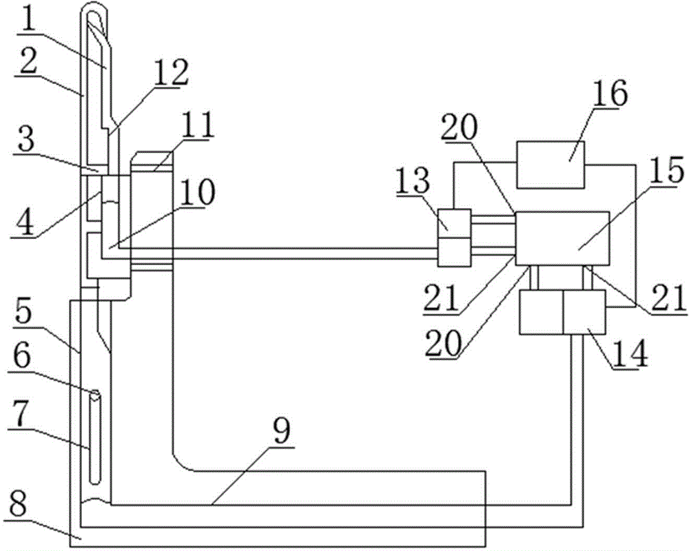
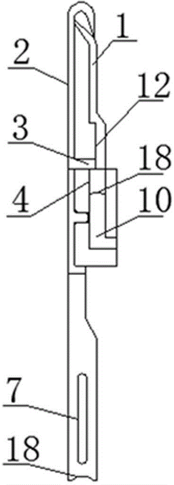
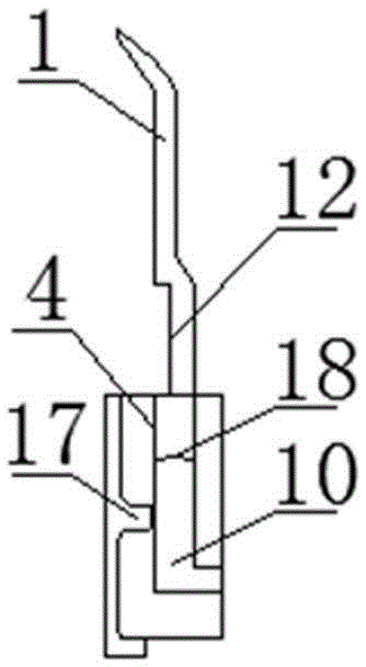
[0014] Referring to the accompanying drawings, a knitting electronic needle includes an inner needle 1, a needle body 2, a needle seat 8, an inner needle slideway 4, an inner needle air path 10, a needle body air path 9, an inner needle control solenoid valve 13, and a needle body Control the solenoid valve 14, the vacuum pump 15 and the program controller 16, the inner needle 1 is installed on the inner needle slideway 4 with a plug-in type, and the inner needle slideway 4 is installed on the needle body 2 with a plug-in type. Needle slideway 4 is provided with recessed hole 17, and described needle body 2 is provided with boss 19, and the recessed hole 17 on the described inner needle slideway 4 matches with the boss 19 on needle body 2, and described needle body 2 The needle body 2 is provided with a needle body limiting groove 7, and the needle holder 8 is provided with a needle body slideway 5, and the needle body 2 is installed on the needle holder through the needle body...


PUM


Abstract

The invention relates to the field of spinning equipment, in particular to an electronic knitting needle for a large-diameter circular knitting machine. The electronic knitting needle comprises an inner needle, a needle body, a needle seat, an inner needle sliding way, an inner needle air path, a needle body air path, an inner needle control electromagnetic valve, a needle body control electromagnetic valve, a vacuum pump and a program controller. The inner needle is installed on the needle body through the inner needle sliding way, the needle body is provided with a needle body limiting groove, the needle seat is provided with a needle body sliding way, the needle body is installed on the needle body sliding way of the needle seat, the inner needle sliding way is connected with the inner needle air path, the vacuum pump is provided with a vacuum opening and a high pressure opening, the needle body sliding way is connected with the needle body air path, and the channel selection of the inner needle control electromagnetic valve and the channel selection of the needle body control electromagnetic valve are controlled by the program controller. By means of the electronic knitting needle, the resource utilization rate is increased, the installing time is shortened, control is simple and reliable, the cost of the knitting machine and the load in the operation process are reduced, and the working efficiency of the knitting machine is improved.

Description

technical field [0001] The invention relates to the field of textile equipment, in particular to an electronic knitting needle used for a large circular knitting machine. Background technique [0002] At present, knitting equipment mainly includes flat knitting machines, circular knitting machines, warp knitting machines, hosiery machines and other types. The needle type can close the needle hook by moving the needle latch or driving the needle core through the pressing plate and yarn. The above situations are all mechanically driven in the driving structure, the control process is complicated, and the energy consumption is high. If weaving different jacquards For different models, different driving cams need to be changed, and disassembly takes time, which affects the weaving speed; common knitting needles include crochet needles, latch needles, slot needles, etc., all of which are installed on the needle bar by the latch through the latch pin. If any part If something goe...

Claims


Application Information

Patent Timeline
IPC IPC(8): D04B35/02
Inventor 宋日升
Owner 烟台宋和宋智能科技股份有限公司
Learn More