
Extrusion blow molding machine-head-and-die-orifice gap electrical adjustment device and realization method and application thereof

An extrusion blow molding and electric adjustment technology is applied in the field of electric adjustment devices for the die gap of extrusion blow molding parison die, which can solve the problems of shortened service life, high production and manufacturing costs, heat generation, etc. Cost reduction and quick response

Active Publication Date: 2013-04-10
SOUTH CHINA UNIV OF TECH
View PDF1 Cites 9 Cited by
  • Summary
  • Abstract
  • Description
  • Claims
  • Application Information

AI Technical Summary

Problems solved by technology

The disadvantage of this method is that in order to realize the axial movement of the mandrel, the motor needs to be switched forward and reverse frequently, which causes serious heat generation and shortens the service life; in addition, for more complex products, it is required to align the die opening within one molding cycle. The gap is adjusted multiple times, so higher requirements are placed on the response speed and load capacity of the motor, and the production and manufacturing costs of the equipment are very high

Method used


Image

  • Extrusion blow molding machine-head-and-die-orifice gap electrical adjustment device and realization method and application thereof
  • Extrusion blow molding machine-head-and-die-orifice gap electrical adjustment device and realization method and application thereof
  • Extrusion blow molding machine-head-and-die-orifice gap electrical adjustment device and realization method and application thereof

Examples


Embodiment

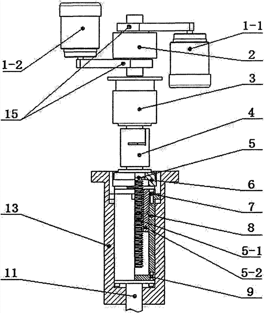
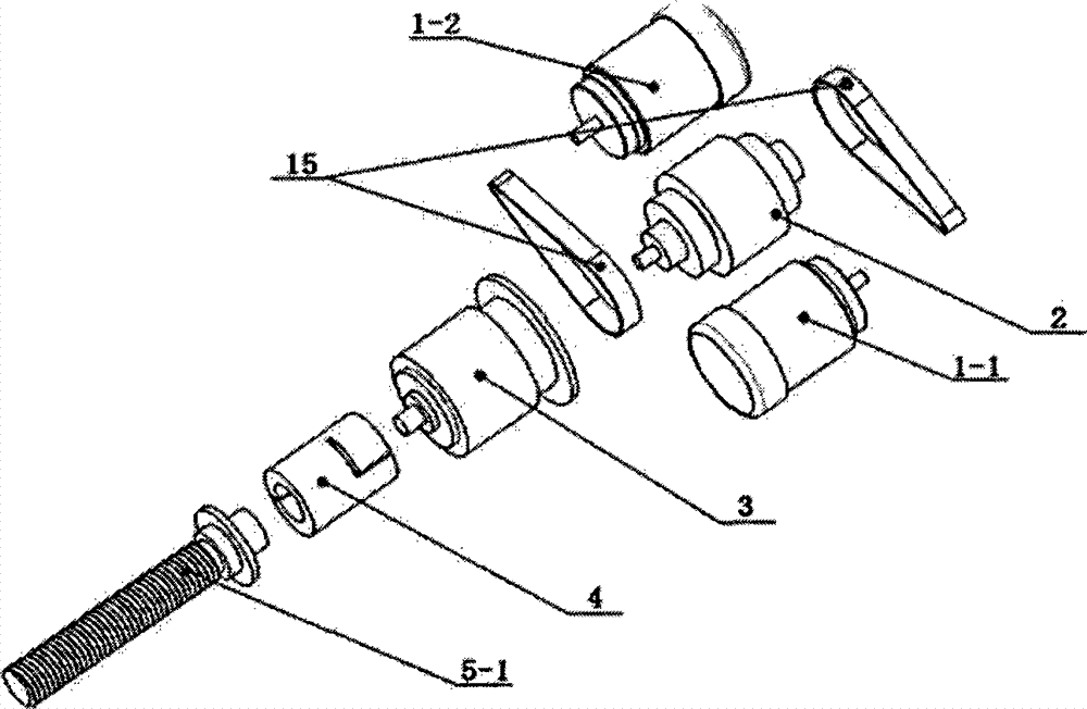
[0026] Concrete structure of the present invention sees Figure 2-7 . Figure 2-7 It is shown that the electric adjustment device for the gap between the die and mouth of the extrusion blow molding machine includes motors 1-1 and 1-2, a synchronous belt 15, a clutch reversing device 2, a reducer 3, a coupling 4, a ball screw pair 5, Thrust roller bearing 6, sleeve 13 with chute, sleeve 8 with Oldham slider, and mandrel 11 connected thereto.

[0027] The clutch reversing device 2 adopts a clutch assembly composed of a forward clutch 2-4, a reverse clutch 2-5 and a brake clutch 2-6, and its forward input end cover 2-2 and reverse input end cover 2-3 are respectively connected to the motors 1-1 and 1-2 through the synchronous belt 15, when the forward clutch 2-4 or the reverse clutch 2-5 is energized and engaged, the output shaft 2-1 and the input end cover 2- 2 or 2-3 are connected to form forward or reverse output; when the brake clutch 2-6 is energized and engaged, the outpu...


PUM


Abstract

The invention provides an extrusion blow molding machine-head-and-die-orifice gap electrical adjustment device. The device comprises motors, a belt, a reversing device, a speed reduction machine, a coupling, a ball screw pair, a thrust roller bearing, a sleeve and a core rod, wherein the belt is a synchronous belt; the reversing device is a clutch reversing device and comprises two input end covers and an output shaft; the two input end covers are connected with two motors through the synchronous belt respectively; the output shaft is connected with the input end of the speed reduction machine; the output shaft of the speed reduction machine is connected with the ball screw pair through the coupling; the sleeve comprises a sleeve with a chute and a sleeve with a cross sliding block; the thrust roller bearing is arranged in the step at the upper end of the sleeve with the chute; the sleeve with the chute and the sleeve with the cross sliding block is arranged coaxially; and the two ends of the sleeve with the cross sliding block is connected with the core rod and a nut of the ball screw pair respectively. The invention simultaneously provides a realization method and application ofthe device. The device has the advantages of high transmission efficiency, precise positioning, environmental friendliness, compact and reliable structure, quick response and the like and is suitablefor popularization in industrial production.

Description

technical field [0001] The polymer material extrusion blow molding technology specifically relates to an electric adjustment device for extrusion blow molding parison head die opening gap and its realization method and application. Background technique [0002] Blow molding is one of the three major molding technologies for polymer materials. When the extrusion blow molding technology was used to form products in the early days, the die opening gap of the parison head was generally unchanged. Due to the different blowing ratios at different positions in the parison axial direction and the influence of parison expansion and vertical stretching, it was difficult to Ensure the uniformity of product wall thickness distribution. Therefore, during the parison molding process, it is necessary to adjust the die gap to control the wall thickness distribution of the parison, so as to obtain a product with a relatively uniform wall thickness distribution. The head-die gap adjustment ...

Claims


Application Information

Patent Timeline
Patent Type & Authority Patents(China)
IPC IPC(8): B29C49/78B29C49/04
Inventor 黄汉雄王泉杰
Owner SOUTH CHINA UNIV OF TECH
Learn More