Operating method of piston type two-way pressure relief valve

A technology of two-way pressure and working method, which is used in safety valves, balance valves, valve devices, etc., can solve problems such as pipelines that cannot be used for two-way flow, and achieve the effects of simple structure, short pressure relief time and stable performance.

Active Publication Date: 2016-10-26
江苏金荣森制冷科技有限公司
View PDF4 Cites 2 Cited by
  • Summary
  • Abstract
  • Description
  • Claims
  • Application Information

AI Technical Summary

Problems solved by technology

However, the pressure relief valves on the market are all one-way pressure relief valves, which require direction selectivity during installation, and are not suitable for two-way flow pipelines.

Method used


Image

  • Operating method of piston type two-way pressure relief valve
  • Operating method of piston type two-way pressure relief valve
  • Operating method of piston type two-way pressure relief valve

Examples


Embodiment 1

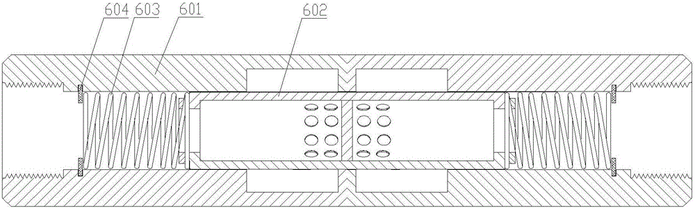
[0037] Embodiment 1. When the pressure at the left end of the piston type two-way pressure relief valve is greater than the pressure at the right end, since the pressure in the piston fluid passage on the left side of the diaphragm is greater than the pressure in the piston fluid passage on the right side of the diaphragm, the fluid pushes the diaphragm toward Move to the right, so that the piston also moves to the right. When the fluid hole on the left side of the partition is located in a fluid channel half cavity on the right side, the fluid with higher pressure flows out from the fluid channel of the piston on the left side through the fluid hole to the right side. A fluid passage on the side half cavity, and then flows into the piston fluid passage on the right, so as to achieve the purpose of pressure relief. At this time, the spring on the left is in a state of tension, and the spring on the right is in a state of compression, until the diaphragm The pressure on the left...

Embodiment 2

[0038] Embodiment 2. When the pressure at the right end of the piston-type two-way pressure relief valve is greater than the pressure at the left end, since the pressure in the piston fluid passage on the right side of the partition is greater than the pressure in the piston fluid passage on the left side of the partition, the fluid pushes the partition to the Move to the left, so that the piston also moves to the left. When the fluid hole on the right side of the partition is located in a fluid channel half cavity on the left side, the fluid with higher pressure flows out from the fluid channel of the piston on the right side through the fluid hole to the left side. A fluid passage on the side half cavity, and then flows into the piston fluid passage on the left, so as to achieve the purpose of pressure relief, at this time, the spring on the right is in tension, and the spring on the left is in compression, until the partition The pressure on the left and right sides is equal...


PUM


Abstract

The invention relates to an operating method of a piston type two-way pressure relief valve. The operating method is characterized in that when the pressure of the left and right ends of the piston type two-way pressure relief valve is the same, a piston is just in the center of a shell, the position of a partition of the piston corresponds to the position of a separating ring plate of the shell, and the piston does not move; when the pressure of the left end of the piston type two-way pressure relief valve is greater than that of the right end of the piston type two-way pressure relief valve, the partition is pushed to move rightwards by fluid, so that the piston moves rightwards, and the purpose of pressure relief is achieved; when the pressure of the right end of the piston type two-way pressure relief valve is greater than that of the left end of the piston type two-way pressure relief valve, the partition is pushed to move leftwards by the fluid, so that the piston moves leftwards, and the purpose of pressure relief is achieved. The operating method has the advantages of capability of achieving two-way pressure relief, simple structure, stable performance, short pressure relief time, high pressure relief speed, high precision and good sealing performance.

Description

technical field [0001] The invention relates to a working method of a piston type two-way pressure relief valve. Background technique [0002] In radiators, cooling systems, hydraulic systems, lubrication systems, oil transmission systems, power systems, mechanical spindles of machine tools, machining centers and liquids, etc.; in the above systems, there are some shocks, pulses, and transients during the flow of liquids. Strict requirements and conditions such as high pressure and large instantaneous flow rate, especially in winter and severe cold areas, the oil used by machinery has high viscosity and poor fluidity when the machine is just started, and has a large impact force, which affects the entire machine and machining center. of paralysis. In order to balance the pressure and release the pressure well without causing damage or scrap to other equipment or other components, there are pressure relief valves on the market to balance the pressure of the system and ensure...

Claims


Application Information

Patent Timeline
Patent Type & Authority Applications(China)
IPC IPC(8): F16K17/18
CPCF16K17/18
Inventor 黄晓军
Owner 江苏金荣森制冷科技有限公司
Why Eureka
Try Eureka