Energy converting device for converting wave energy into electric energy

An energy conversion device and conversion technology, applied in safety devices, ocean energy power generation, transmission device control, etc., can solve problems such as motion stop, failure to achieve electrical output, slow down, etc., to achieve improved electrical energy output, cheap implementation, and avoid feedback effect of effect

Inactive Publication Date: 2011-02-09
HYDAC SYST
View PDF2 Cites 5 Cited by
  • Summary
  • Abstract
  • Description
  • Claims
  • Application Information

AI Technical Summary

Problems solved by technology

Due to the variable nature of wave motion, it has been proven in practice that the associated conversion of mechanical energy into electrical energy is problematic, i.e. a uniform electrical output cannot be achieved and / or due to the feedback process (feedback process), the "mechanical The "wave machine" is stopped, i.e. the movement of the corresponding working cylinder is stopped or at least significantly slowed down

Method used


Image

  • Energy converting device for converting wave energy into electric energy
  • Energy converting device for converting wave energy into electric energy
  • Energy converting device for converting wave energy into electric energy

Examples


Embodiment Construction

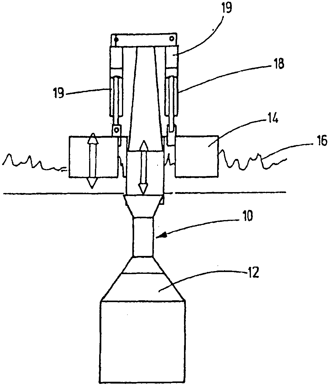
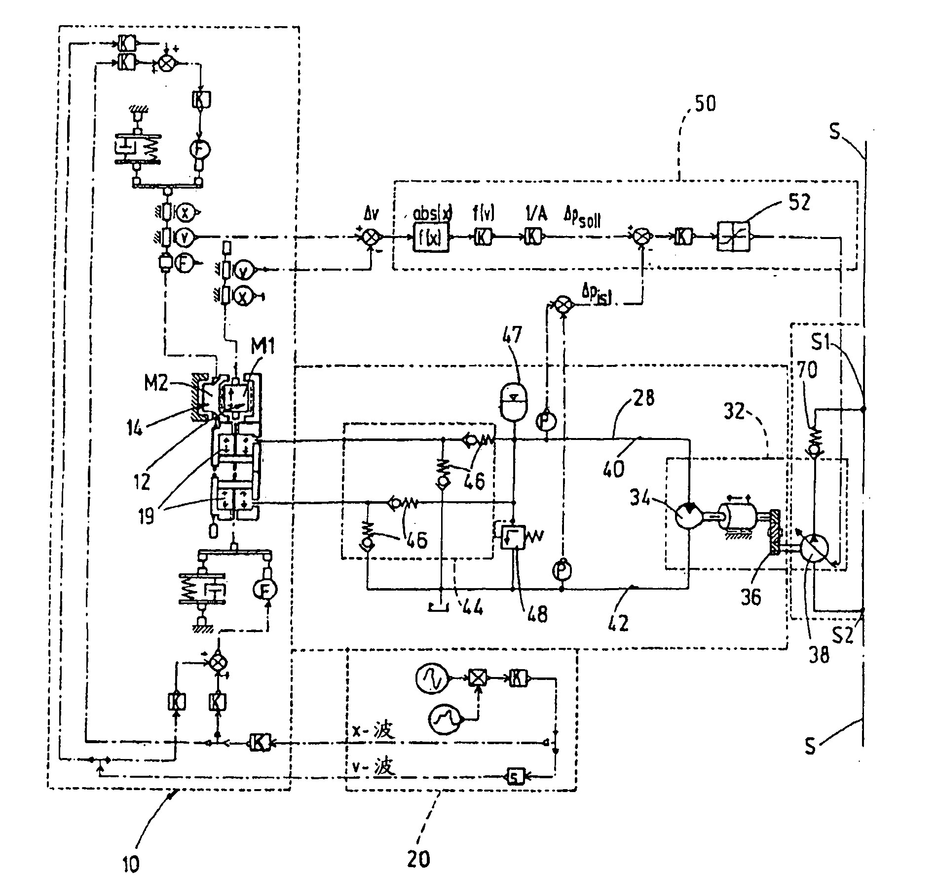
[0017] exist figure 1 The conversion unit, indicated generally at 10 , is designed in the form of a buoy and has, in addition to a so-called pile float 12 , a torus-shaped or ring-shaped float 14 . Due to the different natural frequencies, the two bodies perform relative motion in response to excitation. The different mass motions accompanied by different wave motions are transmitted to a displacement device 18 consisting of individual hydraulic cylinders 19 which are connected on their piston side to the pile float 12 and on their piston rod side to the annular The float 14 is connected. Correspondingly, the conversion unit indicated generally by 10 is in the form of a control circuit diagram image 3 is shown as an example as a spring-mass-vibrator with corresponding damping elements, wherein the waveguide is shown as an example in terms of displacement (X wave) and velocity (V wave) as the overall input signal in the symbolically shown circuit diagram 20 get.

[0018] D...


PUM


Abstract

The invention relates to an energy converting device, particularly for converting mechanical to hydraulic energy, and therefrom into electrical energy, using as an energy transport medium a control fluid guided in two different control circuits having an operative connection to each other by means of a coupling device (32), wherein the one control circuit (28) serves for feeding in energy, particularly in the form of mechanical energy, and the other control circuit serves for discharging energy in the form of converted energy, particularly electrical energy.

Description

technical field [0001] The invention relates to an energy conversion device, in particular for converting mechanical energy into hydraulic energy and hydraulic energy into electrical energy. Background technique [0002] Renewable energy also includes the energy of ocean waves, whose potential energy is estimated to cover roughly 15% of the world's energy needs. Ocean waves themselves are irregular in time and space, but are no less energetic sea motions than, for example, the known tidal range. [0003] The technical conversion for the resulting internal energy can be based here on different principles. A possible conversion principle is based on a two-mass system suspended in water, where the two applied masses have different relative motions caused by wave motions based on their distinct natural frequencies from each other. The relative motion of the corresponding masses relative to one another can be converted into a pumping motion in a working cylinder, for example a ...

Claims


Application Information

Patent Timeline
Patent Type & Authority Applications(China)
IPC IPC(8): F03B15/00F16H61/475F03B13/18
CPCY02E10/38F16H61/475F16H2061/0078F03B13/187F05B2260/406F03B15/00Y02E10/30
Inventor W·哈曼N·伯默尔D·图尔F·黑罗尔德
Owner HYDAC SYST
Why Eureka
Try Eureka