
Rolling wheel device of spiral air pipe machine

An air duct machine and rolling reel technology, which is applied in the field of rolling reel devices, can solve problems such as being unfavorable to production efficiency, costing workers, and cumbersome replacement of rolling reels, and achieves the effects of saving manufacturing costs, simple removal process, and convenient replacement.

Active Publication Date: 2012-10-31
佛山市斯佰诺设备有限公司
View PDF9 Cites 0 Cited by
  • Summary
  • Abstract
  • Description
  • Claims
  • Application Information

AI Technical Summary

Problems solved by technology

[0003] However, the replacement of the reel in the existing reel device is very cumbersome, the bearings, gears, etc. need to be removed to take out the reel, and the bearings and gears must be reinstalled during installation
This will take a lot of time for workers to replace the rolls, which is not conducive to improving production efficiency

Method used


Image

  • Rolling wheel device of spiral air pipe machine
  • Rolling wheel device of spiral air pipe machine

Examples


Embodiment 1

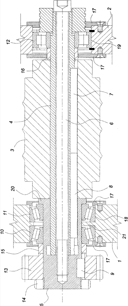
[0020] The rolling device of the spiral air duct machine in this embodiment includes a left vertical plate 1, a right vertical plate 2, a rolling body 3, a rolling shaft 4, a connecting shaft 5, a screw rod 6, a first key 7, and a second key 8 , the third key 9, the first tapered roller bearing 10, the second tapered roller bearing 11, the cylindrical roller bearing 12, the gear 13 as the transmission part, the nut 14 for fixing the gear 13 to the connecting shaft 5, Backing ring 15, backing ring 16 and bearing protection ring 17. The left shaft hole 18 is provided on the left vertical board 1, and the right shaft hole 19 is provided on the right vertical board 2, and the central axis of the left shaft hole 18 is collinear with the central axis of the right shaft hole 19.

[0021] Such as figure 1 As shown, the roller shaft 4 passes through the center of the roller body 3 , and is transmitted with the roller body 3 through the first key 7 . The right end of the roller shaft ...

Embodiment 2

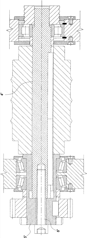
[0027] Such as figure 2 As shown, the difference between this embodiment and Embodiment 1 is: the center of the connecting shaft 5' is provided with a through light hole, and the screw rod 6' passes through the light hole from the left and is connected to the roller shaft 4'.


PUM


Abstract

The invention provides a quick replaceable rolling wheel device. A rolling wheel device of a spiral air pipe machine comprises a left vertical plate, a right vertical plate, a rolling wheel and a transmission part, wherein a left axle hole is formed on the left vertical plate; a right axle hole is formed on the right vertical plate; the rolling wheel is arranged between the left axle hole and theright axle hole; the transmission part drives the rolling wheel; the rolling wheel consists of a rolling wheel body and a rolling wheel shaft which passes through the rolling wheel body; the rolling wheel shaft drives the rolling wheel body through key connection; a connecting shaft of which the axial motion is restricted is arranged in the left axle hole; one end of the rolling wheel shaft is arranged in the right axel hole, and the other end of the rolling wheel shaft drives the connecting shaft by sharing the same central shaft through the key connection; and the transmission part is arranged at the position of the connecting shaft which is extended out of the left vertical plate. As only the rolling wheel body is made of an expensive Cr12 material, the manufacturing cost of the rolling wheel can be greatly saved; and the invention also has the advantages that the rolling wheel device is convenient to replace and is accurately repositioned, so that the work efficiency of workers iseffectively improved.

Description

technical field [0001] The invention relates to a rolling device for rolling ribs on a coiled strip material for a spiral air duct machine. Background technique [0002] The spiral duct machine is a machine that rolls the coiled material into a cylindrical duct. There is a rolling device on the spiral duct machine, and its function is to level the strip material or press the bead on the strip material before the bite forming station. When the thickness of the strip is thick and there is no need to press the ribs on the strip, the rolling device uses a rolling wheel without a beading ring to level the strip; when the thickness of the strip is thin, When it is necessary to press ribs on the strip material to ensure that the air duct processed later has sufficient strength, the rolling device uses a rolling wheel with a ribbing ring, which acts as a ribbing effect on the strip material. Therefore, according to different processing requirements, workers need to choose and inst...

Claims


Application Information

Patent Timeline
Patent Type & Authority Patents(China)
IPC IPC(8): B21D17/04
Inventor 谭阳
Owner 佛山市斯佰诺设备有限公司
Learn More