Lower polishing disk of polishing machine

A technology for polishing discs and polishing machines, which is applied in the direction of wheels, abrasives, and metal processing equipment with flexible working parts, and can solve the problems of uncontrollable changes in the temperature of the polishing discs and no temperature control.

Inactive Publication Date: 2011-02-16
LANZHOU RAPID INDGRPCO
View PDF6 Cites 7 Cited by
  • Summary
  • Abstract
  • Description
  • Claims
  • Application Information

AI Technical Summary

Problems solved by technology

[0003] The throwing plate of the double-sided polishing machine produced before adopts an integral structure without a special temperature control device. The heat generated d

Method used


Image

  • Lower polishing disk of polishing machine
  • Lower polishing disk of polishing machine
  • Lower polishing disk of polishing machine

Examples


Embodiment 1

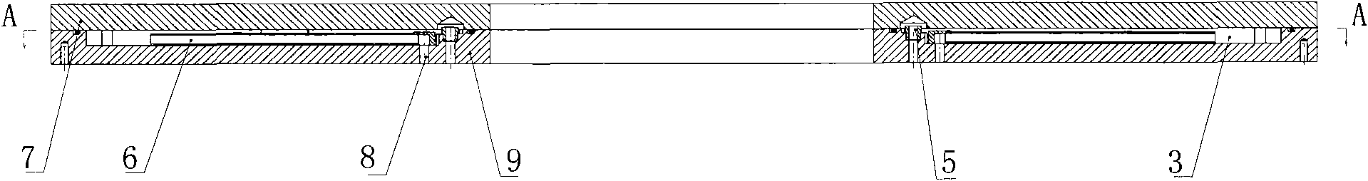
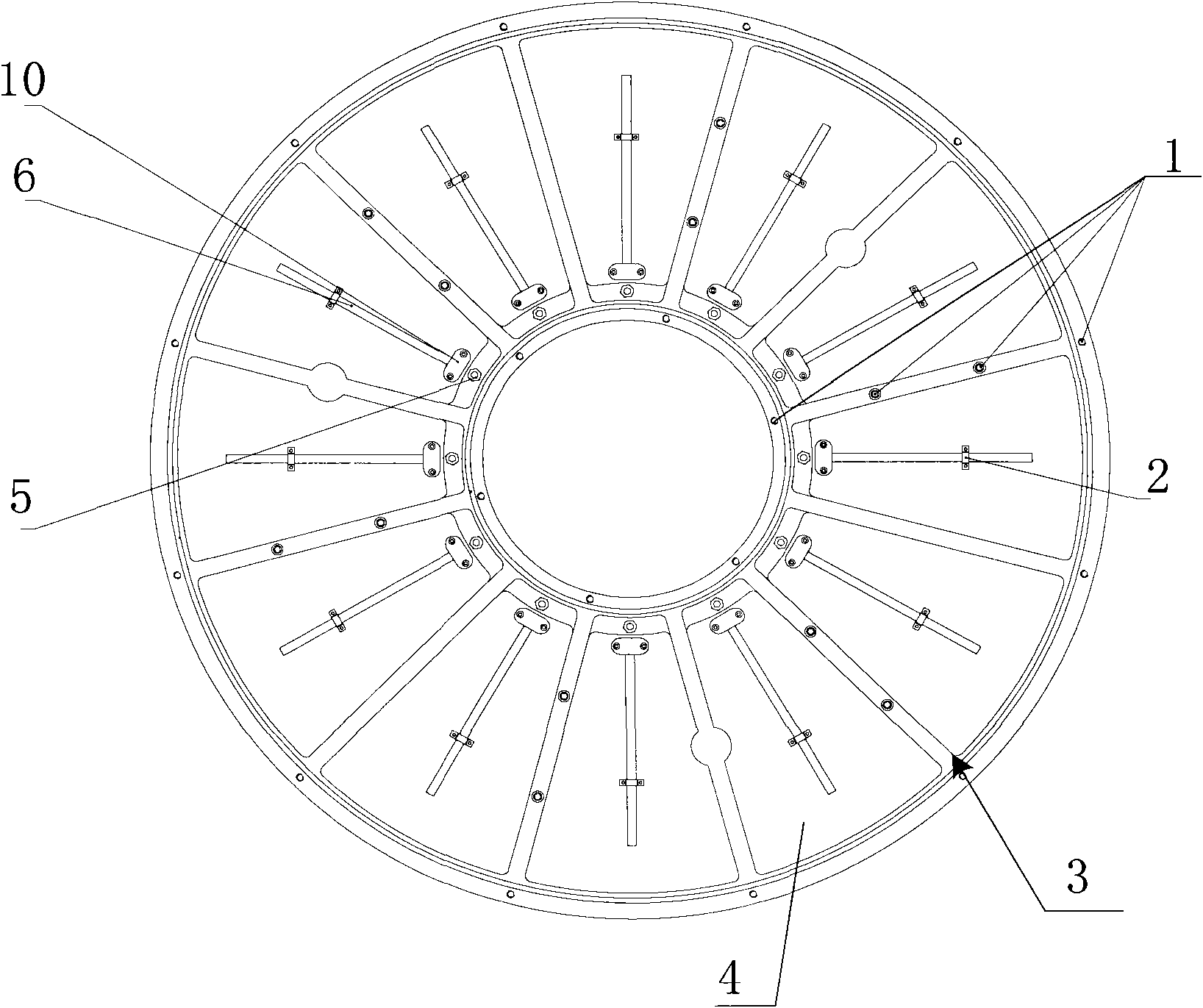
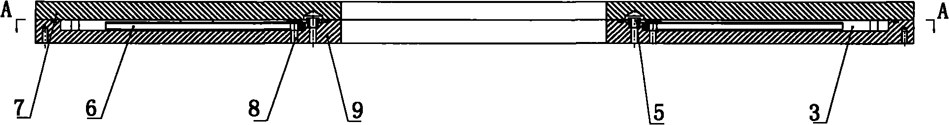
[0017] Embodiment 1: as figure 1 , figure 2 As shown, the lower polishing disc of a polishing machine includes a lower disc working disc 7, and a lower disc base plate 9 is arranged below the lower disc working disc 7, and the connection between the lower disc base disc 9 and the lower disc working disc 7 A cooling cavity 3 is provided between them, and a water inlet 8 and a water outlet 5 are provided on the base plate 9 of the lower plate, and the water inlet 8 and the water outlet 5 communicate with the cooling cavity 3 respectively. The cooling cavity 3 is provided with several sunken fan-shaped areas on the lower plate base plate 9; each sunken fan-shaped area is divided into two sunken cooling zones 4 that communicate with each other by the water inlet pipe 6. The water inlet pipe 6 communicates with the water inlet 8; a water outlet 5 is provided on the inner circle of the base plate 9 of the lower plate. The water inlet pipe 6 communicates with the water inlet 8 thr...


PUM


Abstract

The invention relates to the structure of a silicon wafer lapping machine or a polishing machine, in particular to the structure of a lower polishing disk of a silicon wafer lapping machine or a polishing machine. The lower polishing disk of a polishing machine comprises a lower disk working disk (7), and is mainly characterized by also comprising a lower disk base disk (9) on the lower part of the lower disk working disk (7), wherein a cooling cavity (3) is formed between the lower disk base disk (9) and the lower disk working disk (7); the lower disk base disk (9) is provided with a water inlet (8) and a water outlet (5); and the water inlet (8) and the water outlet (5) are respectively communicated with the cooling cavity (3). The invention has the advantages that the special structure of a water cooling disk can prevent cooling water taking a shortcut; because cooling water can flow out from the water outlet (5) only after the cooling cavity (3) is filled, a polishing disk can be fully cooled by cooling water; and because heat generated by operating is carried out in time, the polishing disk can be forcibly cooled. Compared with a traditional passive cooling method, the invention is more reliable. The lower polishing disk is combined with a precise temperature measuring system and a cooling water flow regulating system to realize the precise control of polishing temperature.

Description

Technical field: [0001] The invention relates to the structure of a silicon wafer grinding machine or polishing machine, in particular to the structure of a polishing disc under the silicon wafer grinding machine or polishing machine. Background technique: [0002] The lower polishing disc used in the silicon wafer polishing machine will generate a lot of heat during the polishing process, and the temperature change will inevitably cause the deformation of the polishing disc, which will affect the processing quality, so the temperature of the polishing disc must be strictly controlled. In recent years, the size of silicon wafers for IC chips tends to be larger in diameter, and the quality requirements for silicon wafers are becoming more and more stringent. For polishing equipment used for double-sided polishing of silicon wafers, the deformation of the throwing plate must be strictly controlled. [0003] The throwing plate of the double-sided polishing machine produced befo...

Claims


Application Information

Patent Timeline
IPC IPC(8): B24D13/14B24D13/18
Inventor 金万斌李方俊梁春
Owner LANZHOU RAPID INDGRPCO
Why Eureka
Try Eureka