Supercharge Your Innovation With Domain-Expert AI Agents!

Round laminated rotor structure for salient pole synchronous motor

A technology of synchronous motor and rotor structure, applied in synchronous machines, magnetic circuit shape/style/structure, electrical components, etc., can solve problems such as high surface temperature, overheating of pole shoe surface, burn-in accidents, etc., and achieve obvious effects, The effect of high rotor strength and high reliability

Inactive Publication Date: 2011-02-16
SEC ELECTRIC MACHINERY
View PDF5 Cites 3 Cited by
  • Summary
  • Abstract
  • Description
  • Claims
  • Application Information

AI Technical Summary

Problems solved by technology

However, the pole shoes of the solid magnetic pole synchronous motor are fastened to the solid magnetic pole with a certain number of bolts, which has certain potential safety hazards. Moreover, when the solid magnetic pole synchronous motor is equipped with a voltage-type frequency converter, due to the large harmonic content in the power supply, the The surface of the solid pole will generate a large additional loss, which will cause the surface of the pole piece to overheat and even burn out the insulation of the pole coil, thus causing serious burn-in accidents
In addition, due to the high surface temperature of the pole shoe, the bolts tightening the pole shoe will also heat up, thereby greatly increasing its tensile stress. When the centrifugal force of the pole shoe is greater than the tensile force that the bolt can bear, the bolt will be pulled off, causing serious accidents

Method used


Image

  • Round laminated rotor structure for salient pole synchronous motor
  • Round laminated rotor structure for salient pole synchronous motor

Examples


Embodiment Construction

[0009] The specific embodiments of the present invention will be further described below in conjunction with the accompanying drawings.

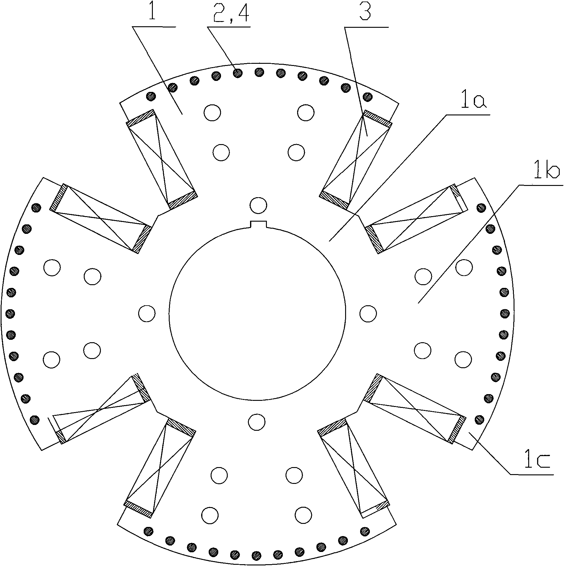
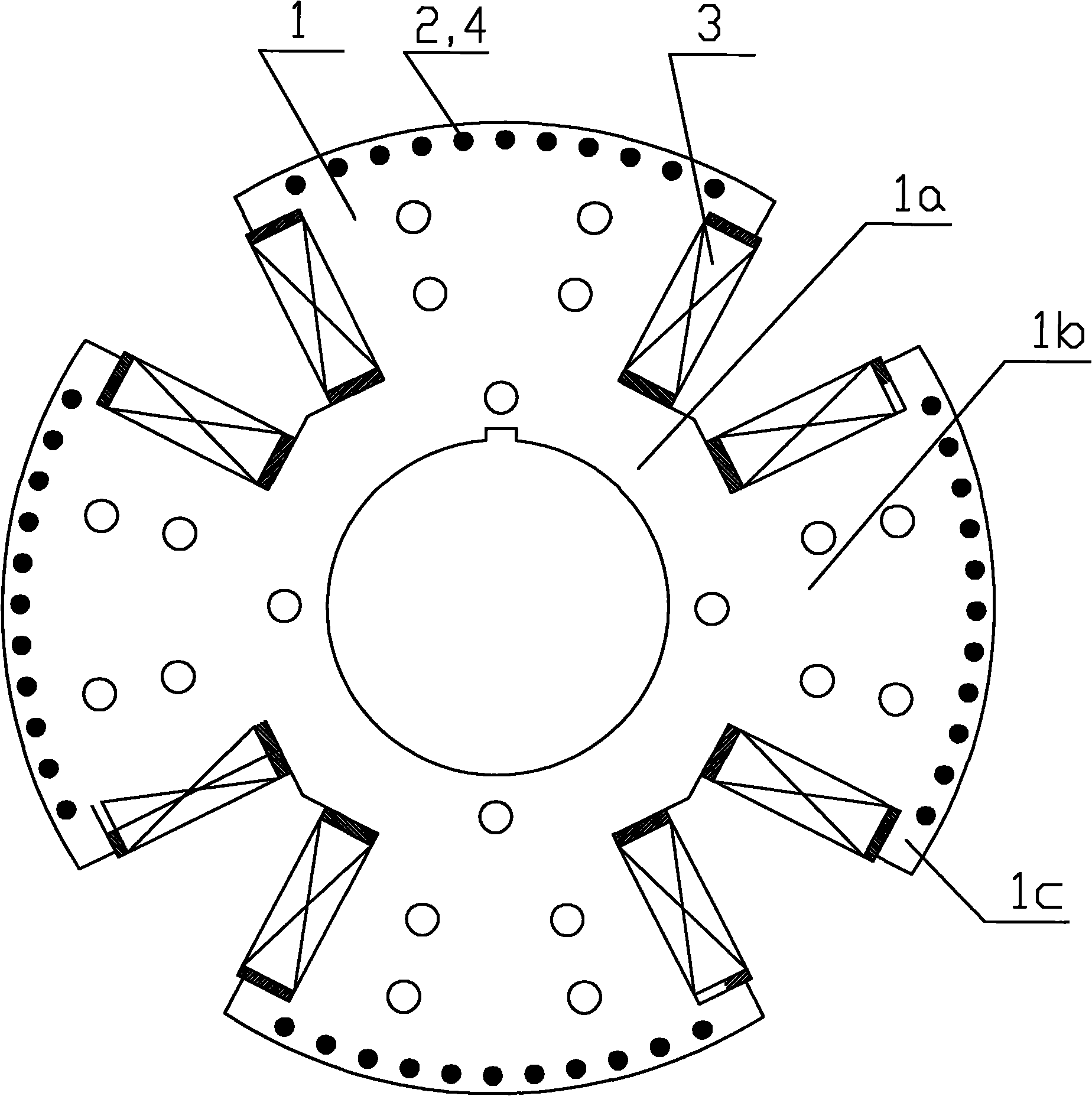
[0010] like figure 1 As shown, the present invention includes laminated core punches 1 , damping rods 2 and magnetic pole coils 3 . The iron core punching piece 1 is a full-circle punching piece in which the yoke 1a and the magnetic pole 1b are integrated. The magnetic pole 1b is radially distributed on the yoke 1a, and the damping hole 4 is punched on the pole shoe 1c of the magnetic pole 1b. The damping rod 2 Placed in the damping hole 4, the magnetic pole coil 3 is nested on the pole body of the magnetic pole 1b. Then use a damping ring (not shown in the figure) to short-circuit the damping rod 2 to form a full damping structure, and the magnetic pole coils 3 are connected through inter-pole connecting lines.

[0011] Description of working principle: The rotor core of the present invention is formed by laminating a certain number of 1-...


PUM


Abstract

The invention relates to a round laminated rotor structure for a salient pole synchronous motor. The structure comprises laminated iron core stampings, a damping rod and a pole coil, wherein the laminated iron core stampings are round stampings; a magnetic pole on the stampings is radial; a round damping hole for placing the damping rod is stamped on the magnetic pole; and the damping rod and the pole coil are respectively arranged in the damping hole and the pole body of the magnetic pole. The round laminated rotor structure for the salient pole synchronous motor has a simple structure and high reliability and fills a gap of a laminated rotor for a large-scale high-speed salient pole synchronous motor in domestic motor industry.

Description

technical field [0001] The invention relates to a salient-pole synchronous motor rotor, in particular to a large-scale high-speed salient-pole synchronous motor rotor. Background technique [0002] At present, the main drive mills of steel rolling high-speed wire rod engineering all use synchronous motors with a speed of 1000-1500rpm, or even 1800rpm. Due to the high speed and limited by the insufficient strength of the rotor laminated magnetic poles, domestic motor manufacturers have made synchronous motors with solid magnetic poles to solve the problem of insufficient strength of the laminated magnetic poles. However, the pole shoes of the solid magnetic pole synchronous motor are fastened to the solid magnetic pole with a certain number of bolts, which has certain potential safety hazards. Moreover, when the solid magnetic pole synchronous motor is equipped with a voltage-type frequency converter, due to the large harmonic content in the power supply, the The surface of ...

Claims


Application Information

Patent Timeline
Patent Type & Authority Applications(China)
IPC IPC(8): H02K1/24H02K19/00
Inventor 王岗
Owner SEC ELECTRIC MACHINERY
Features
  • R&D
  • Intellectual Property
  • Life Sciences
  • Materials
  • Tech Scout
  • Unparalleled Data Quality
  • Higher Quality Content
  • 60% Fewer Hallucinations
Learn More