
High-pressure pump

A technology for high-pressure pumps and pump assemblies, which is applied in the directions of pumps, multi-cylinder pumps, fuel injection pumps, etc., can solve the problem of occupying the structural space of the pump casing, and achieve the effects of compact implementation, reliable orientation and high efficiency

Inactive Publication Date: 2011-02-16
ROBERT BOSCH GMBH
View PDF5 Cites 3 Cited by
  • Summary
  • Abstract
  • Description
  • Claims
  • Application Information

AI Technical Summary

Problems solved by technology

[0003] The high-pressure pump known from DE 10 2005 046 670 A1 has the disadvantage that the return spring, which has to be designed relatively rigidly, takes up considerable installation space in the pump housing
Therefore, there are some restrictions when designing high-pressure pumps

Method used


Image

  • High-pressure pump
  • High-pressure pump
  • High-pressure pump

Examples


Embodiment Construction

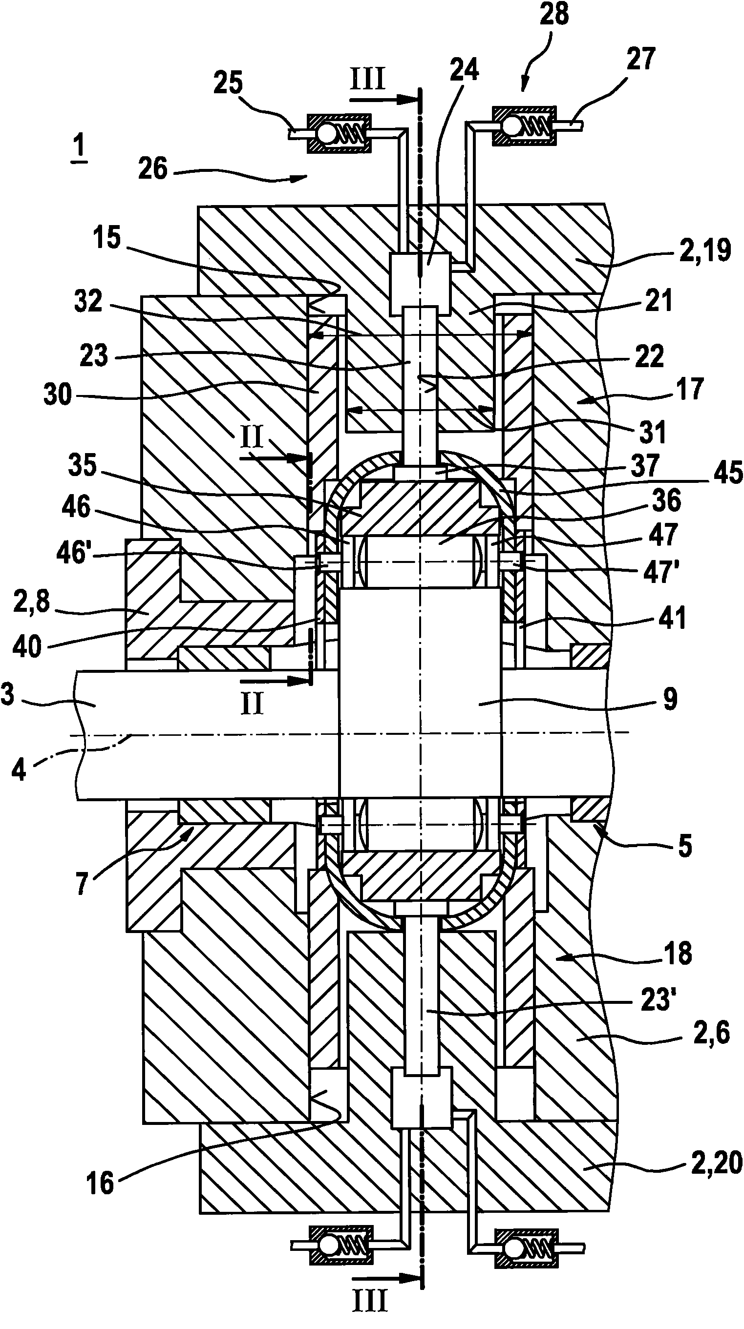
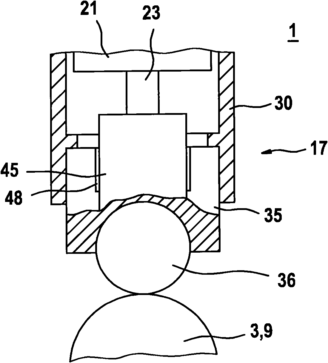
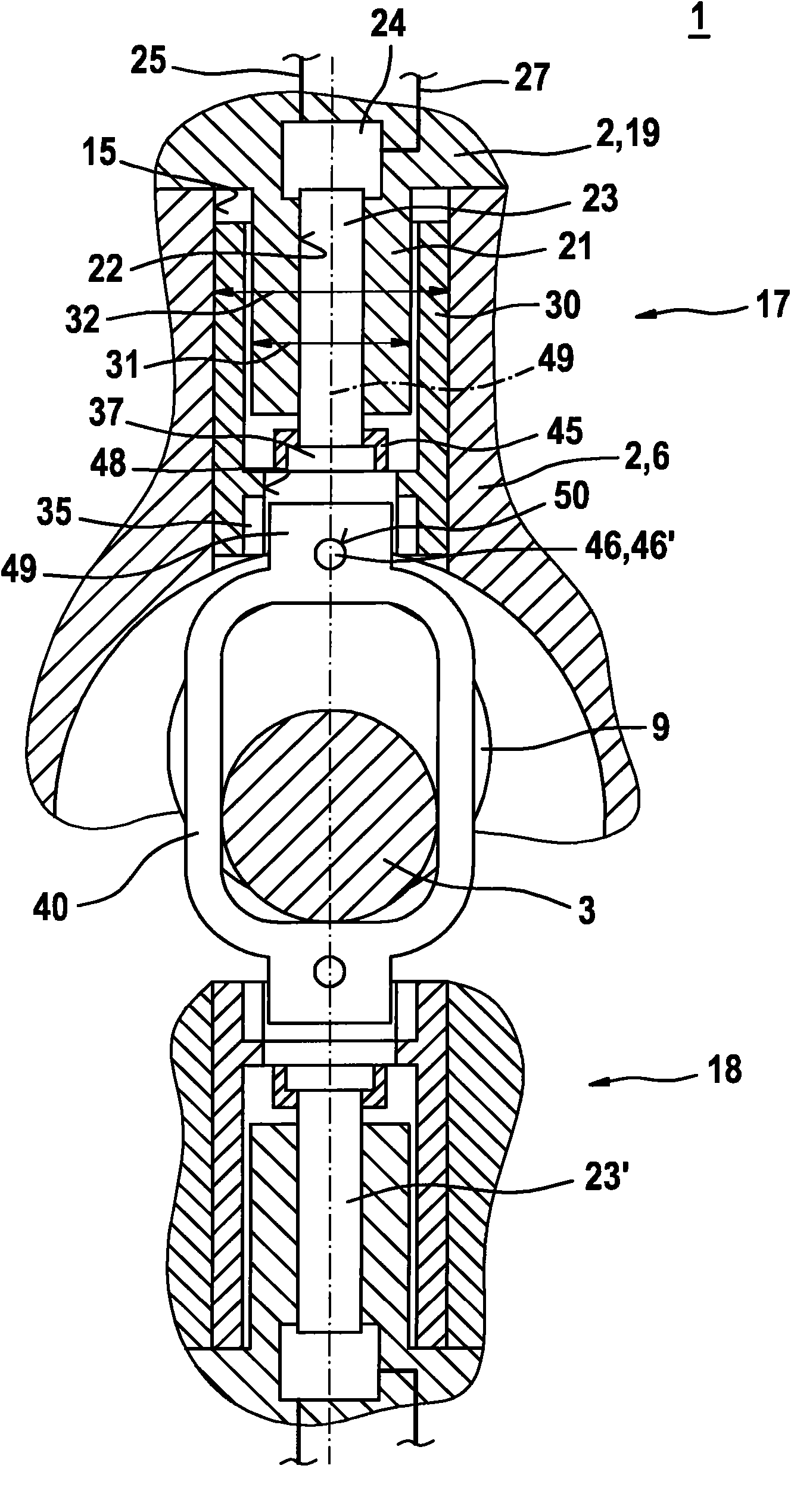
[0018] figure 1 A high-pressure pump 1 according to a first exemplary embodiment of the invention is shown in an axial partial section. The high-pressure pump 1 can be used in particular as a fuel pump for a fuel injection system of an air-compressed self-ignition internal combustion engine. The high-pressure pump 1 is preferably used in a fuel injection system with a fuel distribution plate, the so-called common rail, which stores diesel fuel under high pressure. However, the high-pressure pump 1 according to the invention is also suitable for other uses.

[0019] The high-pressure pump 1 has a multi-part housing 2 . The high-pressure pump 1 also has a drive shaft 3 which rotates about its axis 4 during operation. On the one hand, the drive shaft 3 is supported at bearing points 5 in the base body 6 of the housing 2 . On the other hand, the drive shaft 3 is supported at a bearing point 7 in a flange part 8 of the housing 2 connected to the base body 6 . The two bearing p...


PUM


Abstract

A high-pressure pump (1) is used especially as a fuel pump for fuel injection systems in air-compressing, self-igniting internal combustion engines. Said high-pressure pump (1) comprises a first pump subassembly (17), a second pump subassembly (18), and a drive shaft (3). The first pump subassembly (17) is located at least approximately across from the second pump subassembly (18) in relation to the drive shaft (3). At least one cam (9) for driving both the first pump subassembly (17) and the second pump subassembly (18) is provided on the drive shaft (3). Furthermore, spring elements (40, 41) are provided which are connected to a piston (23) of the first pump subassembly (17) by means of a retaining brace (45) and are connected to a piston (23) of the second pump subassembly (18). The spring elements (40, 41) are mounted in a biased manner such that the two pistons (23, 23) return without separate return springs or retracting springs during operation of the high-pressure pump (1).

Description

technical field [0001] The invention relates to a high-pressure pump, in particular a fuel pump for a fuel injection device. The invention relates in particular to a high-pressure pump for a fuel injection system of an air-compressed, self-ignition internal combustion engine. Background technique [0002] A high-pressure pump for a fuel injection system of an internal combustion engine is known from DE 10 2005 046 670 A1. The known high-pressure pump has a pump housing, in which a pump element is arranged, the pump element has a reciprocating pump piston driven by a drive shaft, the pump piston is located in a part of the pump housing The cylinder bore is displaceably guided and a pump working chamber is defined in the cylinder bore. The pump piston is supported on the drive shaft via a hollow cylindrical hammer, wherein the hammer is guided displaceably in a bore in a part of the pump housing in the direction of the longitudinal axis of the pump piston. A return spring i...

Claims


Application Information

Patent Timeline
IPC IPC(8): F04B1/04F02M59/10F02M59/48F02M59/06F02M59/44
CPCF04B1/0439F02M59/06F02M59/48F02M59/102F02M59/44F04B1/0426F01L2307/00
Inventor F·伯金
Owner ROBERT BOSCH GMBH
Learn More