Circuit breaker

A circuit breaker, pivoting technology, applied in the direction of circuits, parts of protection switches, electrical components, etc., can solve the problems of scratching members and inclined surfaces wear, unstable handle operation, and undurable fast approaching units.

Active Publication Date: 2011-02-16
MATSUSHITA ELECTRIC WORKS LTD
View PDF4 Cites 10 Cited by
  • Summary
  • Abstract
  • Description
  • Claims
  • Application Information

AI Technical Summary

Problems solved by technology

However, the circuit breaker in Japanese Patent Laid-Open Document No. 2637081 drives the scraper member to slide on the inclined surface through the handle every time the switch is switched on

Method used


Image

  • Circuit breaker
  • Circuit breaker
  • Circuit breaker

Examples


Embodiment Construction

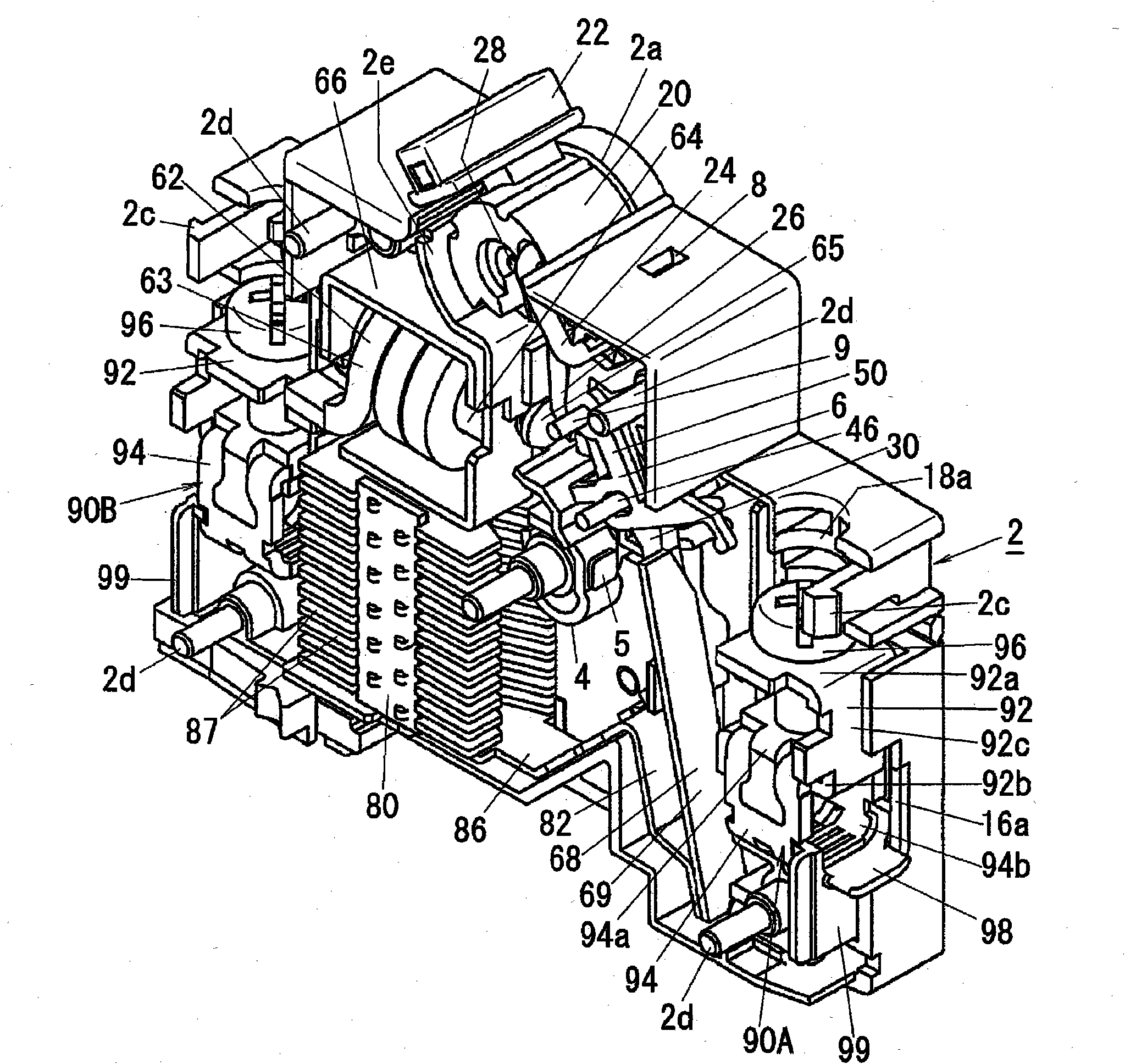
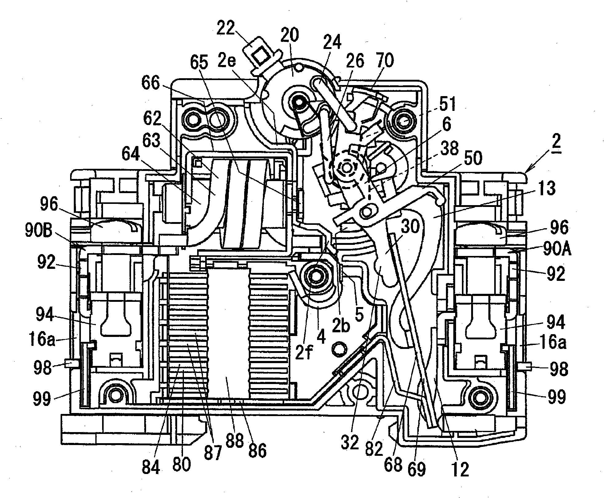
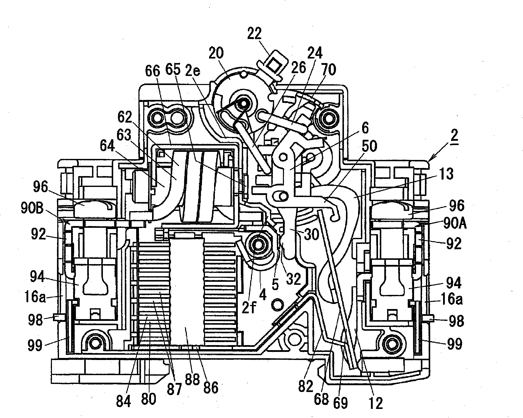
[0033] Next, the circuit breaker in this embodiment will be described with reference to the drawings. The circuit breaker in this embodiment includes a housing 1, a fixed contact 5, a movable contact 32, a handle 20 made of synthetic resin, a switching unit 6, a tripping device (namely, an electromagnetic tripping device 62 and a thermal tripping device 68 ), an indicator 70 made of synthetic resin, an arc extinguisher 80, a power supply side terminal 90A, and a load side terminal 90B. The switching unit 6 is configured to connect and disconnect the movable contact 32 with the fixed contact 5 in response to a pivoting operation (opening and closing operation) of the handle 20 . The tripping device is configured to trip the switching unit 6 when detecting an abnormal current (short circuit current, overload current) flowing between the movable contact 32 and the fixed contact 5 to forcibly connect the movable contact 32 to the fixed contact 5. Contact 5 separates. The indicat...


PUM


Abstract

Provided is a circuit breaker which can quicken the opening/closing speed of a contact and can maintain the performance over a long term. A circuit breaker is constituted such that when a handle is operated to turn about a second rotary shaft 9 of a supporting arm 40 from an off position toward an on position , a second interlock link 26 regulates rotation of a movable bar 30 while resisting against the urging force of a spring member 38 in order to prevent the movable bar 30 from rotating a predetermined angle or more about a first rotary shaft 46 within a predetermined angular range in rotation of the supporting arm. Furthermore, when the supporting arm 40 rotates over a predetermined angular range to the on position, the second interlock link 26 disengages from the movable bar 30 and the movable bar 30 is rotated about the first rotary shaft 46 by the urging force of the spring member 38 thus closing a movable contact 32 to a fixed contact 5.

Description

technical field [0001] The present invention relates to circuit breakers. Background technique [0002] A circuit breaker has been proposed for connection and disconnection between movable contacts and fixed contacts in response to handle operation and overload current. The circuit breaker disclosed in Japanese Patent Laid-Open Document No. 2637081 is provided with a connection unit for associating handle operation with connection and disconnection between movable contacts and fixed contacts, and a trip lever. , the trip bar is configured to lock the connection unit and trip the blocking unit in response to the detected overload current. The circuit breaker is designed to trip the connection unit when one end of the connection unit is pushed by an electromagnetic trip device or a thermal trip device in the presence of an overload current, thereby forcibly separating the movable contact from the fixed contact. [0003] When the movable contacts are slowly connected or disco...

Claims


Application Information

Patent Timeline
IPC IPC(8): H01H73/50
CPCH01H71/501H01H73/50H01H71/04H01H71/526
Inventor 水野初男
Owner MATSUSHITA ELECTRIC WORKS LTD
Why Eureka
Try Eureka