
Automatic bottom line changing device of computer embroidery machine

An embroidery machine and automatic technology, which is applied to the mechanism of the embroidery machine, embroidery machine, bobbin winding in the sewing machine, etc., can solve the problems of reducing the labor intensity of workers, increase the complexity of the equipment, improve the degree of automation, and reduce the workload Effect

Inactive Publication Date: 2011-02-23
FOSHAN QICHUANG TECH DEV
View PDF5 Cites 21 Cited by
  • Summary
  • Abstract
  • Description
  • Claims
  • Application Information

AI Technical Summary

Problems solved by technology

[0004] This shuttle changing mechanism saves the man-hours spent on manual shuttle changing, but there is still a large space for improving the production efficiency of the equipment
If it is still necessary to manually replenish the spare rotary hooks in time, this process still requires a certain amount of work, which limits the workers on duty to take care of more machines, and fails to reduce the labor intensity of workers more effectively.

Method used


Image

  • Automatic bottom line changing device of computer embroidery machine
  • Automatic bottom line changing device of computer embroidery machine
  • Automatic bottom line changing device of computer embroidery machine

Examples


Embodiment Construction

[0027] The present invention is described in further detail by the following examples.

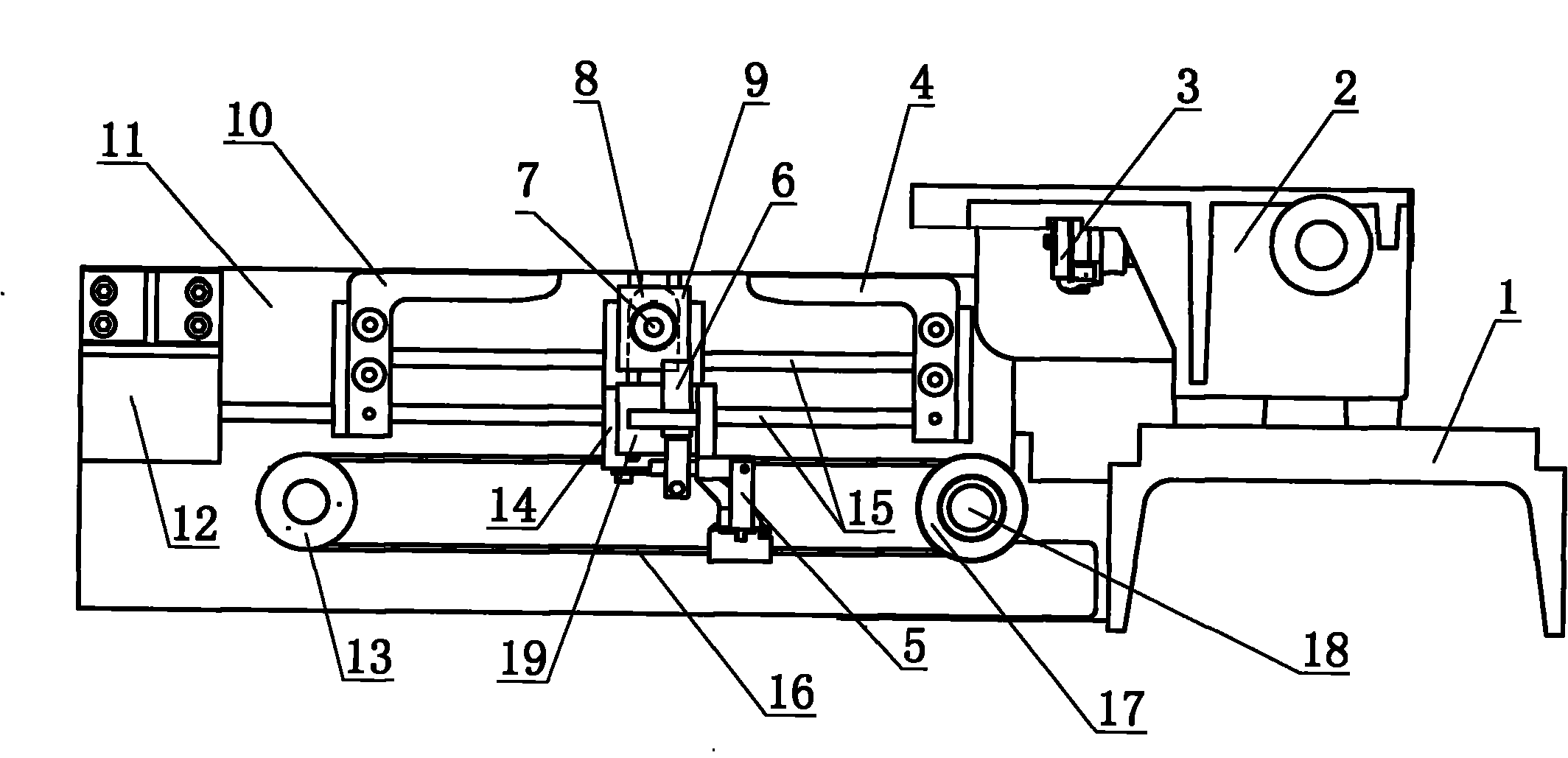
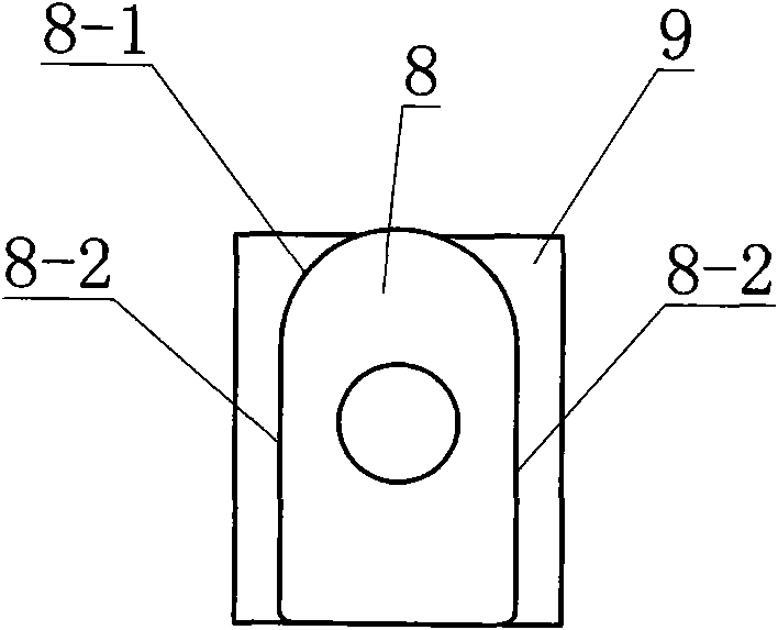
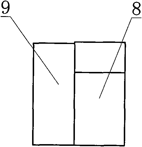
[0028] see Figure 1-Figure 4 As shown, an automatic bobbin thread changing device of a computerized embroidery machine is composed of a frame 1, a rotary hook box 2, a rotary hook 3, a bobbin storehouse 12 and its spare bobbin, a first guide plate 4, a second guide plate 10, an installation Plate 11, slide table 14, cylinder 6, bobbin claw 5, rotating block 9, positioning rotating block 8, horizontal guide bar 15 and horizontal belt transmission mechanism are formed. The hook 3 is placed in the hook box 2, the hook box 2 is fixed on the frame 1, and a mounting plate 11 is fixedly installed on the frame 1, one end of the mounting plate 11 is close to the hook box 2, and the mounting plate 11 The other end is fixed with bobbin chamber 12. On the mounting plate 11, two first guide plates 4 and the second guide plate 10 with the same shape and installed facing each other are fixedly install...


PUM


Abstract

The invention discloses an automatic bottom line changing device of a computer embroidery machine, which can automatically change a shuttle peg of a bottom line rotating shuttle in a mechanical mode so as to further improve the production efficiency and the automation degree of the computer embroidery machine and lighten the labor intensity of workers. Therefore, a mounting plate is fixedly arranged on a machine frame; one end of the mounting plate is close to a rotating shuttle box, while the other end of the mounting plate is fixedly provided with a shuttle peg bin; two right angle type guide plates, which have the same shape and are opposite to each other, are arranged in the mounting plate; the outer side of the lower lateral surface of a horizontal section of the guide plate is provided with a sliding block; the upper part of the sliding block is provided with a rotary block and a positioning rotary block; the upper end face of the positioning rotary block is a semicircle surface, two lateral surfaces of the positioning rotary block are planes parallel to each other, and the positioning rotary block contact a limit track formed by the lower lateral surfaces of the horizontal sections of the two guide plates; a cylinder and a shuttle peg paw are vertically arranged on the left lower part of the rotary block; and the sliding block performs horizontal linear reciprocating motions with the help of a guide rod and a belt driving structure, thereby making the shuttle peg paw perform circular track motions between the shuttle peg box and the shuttle peg bin to realize the bottom line automatic changing.

Description

technical field [0001] The invention relates to the technical field of computerized embroidery bobbin thread changing, in particular to an automatic bobbin thread changing device for a computerized embroidery machine. Background technique [0002] So far, the computerized embroidery machines used in China generally do not have the function of automatically replenishing the bottom thread. The bobbin thread of the embroidery machine is wound on the thread core contained in the bobbin core. When the bobbin thread is used up at a certain head of the machine, it must be stopped and manually operated to remove the bobbin thread from the bobbin case. Replace the bobbin with a new one with the bobbin fully wound with the bobbin thread, or take out the empty bobbin from the bobbin and replace it with a full bobbin. Simultaneously, the rotary hook box is generally all located under the worktable, and it is very inconvenient to replace the action. Calculated on the basis of each comp...

Claims


Application Information

Patent Timeline
IPC IPC(8): D05C11/18
CPCD05C11/18D05B59/04
Inventor 梁国杰
Owner FOSHAN QICHUANG TECH DEV
Learn More