Hydraulic support loading platform

A hydraulic support and platform technology, applied in pillars/supports, mining equipment, earthwork drilling and mining, etc., can solve problems such as loading chambers, poor sanitation of working faces, increased safety uncertainty, and wire ropes are easy to be pulled off, etc. , to achieve the effects of enhancing adaptability, reducing the possibility of spontaneous combustion of coal seams, and improving the degree of civilization

Inactive Publication Date: 2011-02-23
枣庄矿业(集团)付村煤业有限公司
View PDF7 Cites 4 Cited by
  • Summary
  • Abstract
  • Description
  • Claims
  • Application Information

AI Technical Summary

Problems solved by technology

[0002] The traditional hydraulic support loading method is as follows: Figure 9 , Figure 10 As shown in the figure, a heavy-duty lifting shed is set up within 20 meters from the working face, and three strings of moving pulleys are used to lift the hydraulic support on both sides of the lifting shed, and the hydraulic support is pulled out along the bottom plate of the working face to the lifting shed. Combined with the hook for lifting, when using this method, there are more prominent problems in the removal and loading of the hydraulic support: ① When dragging, a large amount of floating gangue and floating coal will be plowed up, resulting in poor sanitation in the loading chamber and working surface
②Due to the high friction between the hydraulic support and the bottom plate of the working face, it is easy to be damaged during dragging, and the wire rope is easily broken
③Using the hoisting greenhouse needs to overcome the gravity of the hydraulic support itself for hoisting and loading, which increases the uncertainty of safety (it is easy to reproduce the phenomenon of falling shed, collapsing hook, biting the rope, etc.)
④Complicated working links, slow loading speed and high labor intensity
⑤The efficiency of the working surface is low

Method used


Image

  • Hydraulic support loading platform
  • Hydraulic support loading platform
  • Hydraulic support loading platform

Examples


Embodiment Construction

[0027] The present invention will be further described below in conjunction with accompanying drawing and specific embodiment:

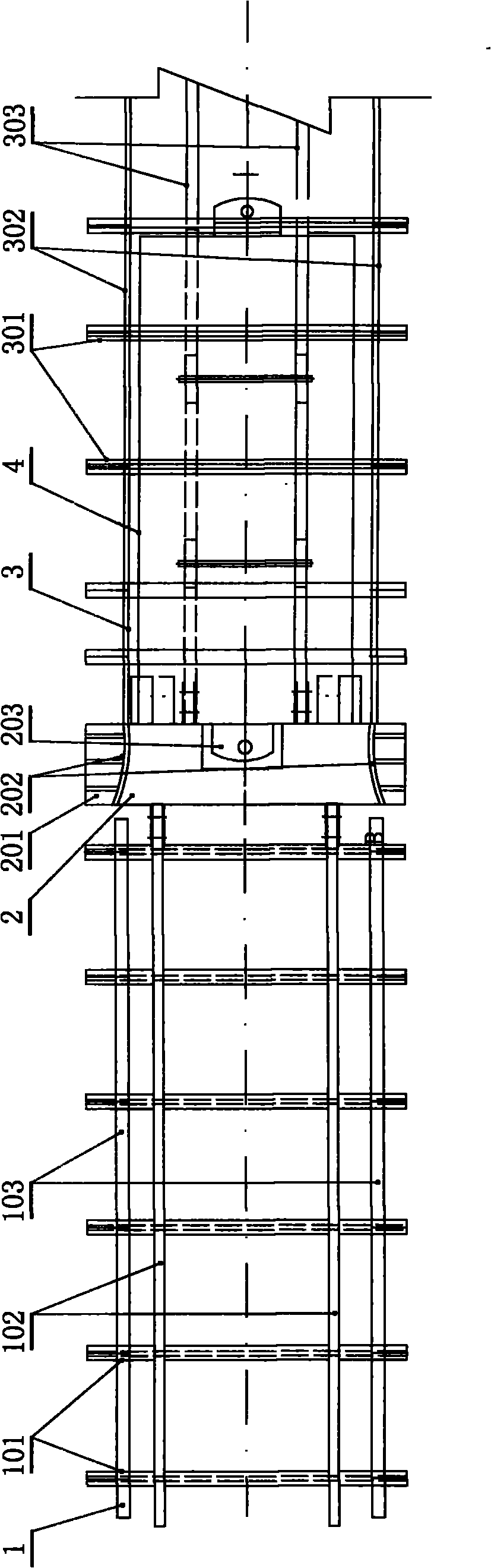
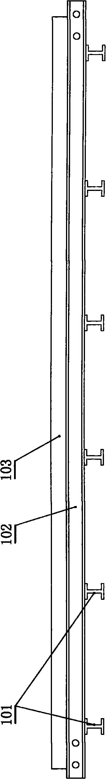
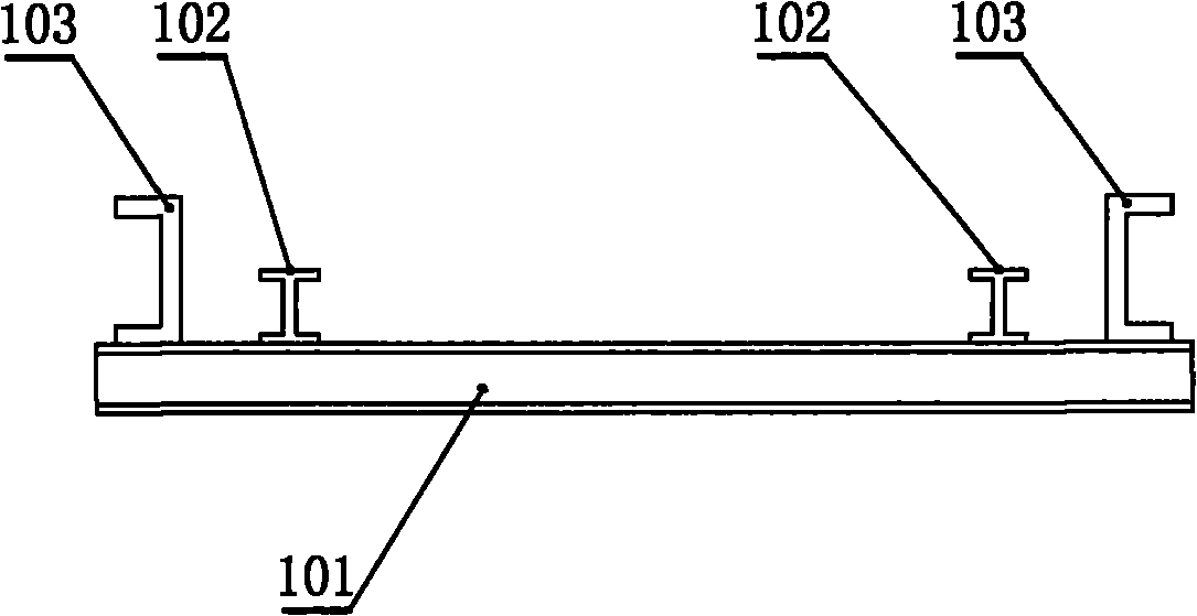
[0028] A hydraulic support loading platform, such as Figure 1 to Figure 7 As shown, it includes a connecting platform 2, one side of the connecting platform 2 is connected with a guiding ladder road 1, and the other side of the connecting platform 2 is connected with a limit frame 3, and the guiding ladder road 1 includes a ladder-shaped base 101, on which the ladder-shaped base 101 is connected. The guide rail 102 and the guide baffle 103 are welded, and the guide baffle 103 is located outside the guide rail 102; the limit frame 3 includes a limit base 301, and the limit base 301 is welded with a flatbed car track 303 and a limit baffle 302, the limit baffle 302 is located on the outside of the flatbed car track 303; the connecting platform 2 includes a base 201, one side of the base 201 is welded with a guide ladder road connecting plate 204, and ...


PUM


Abstract

The invention relates to a hydraulic support loading platform which is safe, sanitary and convenient to use and has high operating efficiency. The hydraulic support loading platform comprises a connection platform, wherein a guiding ladder road is connected to one side of the connection platform, and a limiting frame is connected to the other side of the connection platform; the guiding ladder road comprises a ladder-shaped base, and a guiding rail and a guiding baffle plate which are welded on the ladder-shaped base, and the guiding baffle plate is positioned on the outer side of the guiding rail; the limiting frame comprises a limiting base, and a flat-bed trailer rail and a limiting baffle plate which are welded on the limiting base, and the limiting baffle plate is positioned on the outer side of the flat-bed trailer rail; the connection platform comprises a base; a connection plate of the guiding ladder road is welded to one side of the base, and a connection plate of the limiting frame and an anti-vibration platform are welded to the other side of the base; the connection plate of the guiding ladder road is fixedly connected with the guiding rail; the connection plate of the limiting frame is fixed connected with the flat-bed trailer rail; a flat-bed trailer positioning groove is formed on the base, and an opening of the flat-bed trailer positioning groove faces one side on which the limiting frame is positioned; and an arc-shaped baffle plate is welded on the base.

Description

technical field [0001] The invention relates to a vehicle loading platform, in particular to a hydraulic support vehicle loading platform. Background technique [0002] The traditional hydraulic support loading method is as follows: Figure 9 , Figure 10 As shown in the figure, a heavy-duty lifting shed is set up within 20 meters from the working face, and three strings of moving pulleys are used to lift the hydraulic support on both sides of the lifting shed, and the hydraulic support is pulled out along the bottom plate of the working face to the lifting shed. Combined with the hook for lifting, when using this method, there are more prominent problems in the removal and loading of the hydraulic support: ① When dragging, a large amount of floating gangue and floating coal will be plowed up, resulting in poor sanitation in the loading chamber and working surface. ②Due to the high friction between the hydraulic support and the bottom plate of the working face, it is easy t...

Claims


Application Information

Patent Timeline
Patent Type & Authority Applications(China)
IPC IPC(8): E21D15/60
Inventor 李玉华闫业臣魏谦牟国礼刘向东王子炎江继红李强
Owner 枣庄矿业(集团)付村煤业有限公司
Why Eureka
Try Eureka