Method and device for conveying combustible gas generated in leachate treatment

A conveying device and leachate technology, which is used in gas/liquid distribution and storage, pipes/pipe joints/fittings, and pipe heating/cooling, etc. To reduce the possibility of spontaneous combustion and explosion, improve the absorption effect, and reduce the effect of spontaneous combustion or explosion

Active Publication Date: 2020-03-17
瀚蓝(福清)固废处理有限公司
View PDF7 Cites 2 Cited by
  • Summary
  • Abstract
  • Description
  • Claims
  • Application Information

AI Technical Summary

Problems solved by technology

[0004] After burning garbage, many complex gases will be produced, including flammable gases such as SO2 and HCl. These gases are prone to spontaneous combustion or even explosion at high temperature or in a state of sufficient oxygen. At the same time, the gas obtained after combustion is usually It is a high-temperature gas, which poses a great safety hazard during transportation and poses a threat to the personal health of the staff. Once the gas leaks due to spontaneous combustion or explosion, the gas generated is more complicated, and the gas diffuses. It is also harmful to the safety of nearby residents. There are certain hidden dangers, and at the same time, it will cause environmental pollution

Method used


Image

  • Method and device for conveying combustible gas generated in leachate treatment
  • Method and device for conveying combustible gas generated in leachate treatment
  • Method and device for conveying combustible gas generated in leachate treatment

Examples


Embodiment 1

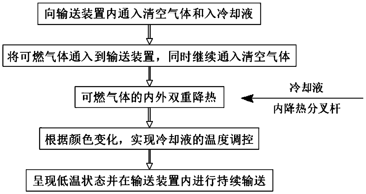
[0048] see figure 1 , a method for transporting combustible gas produced by leachate treatment, comprising the following steps:

[0049] S1. First, pass clear air into the conveying device, discharge the air inside, and pass coolant into the conveying device;

[0050] S2. Pass the combustible gas produced by the incinerator waste incineration into the conveying device, and continue to pass in the clear gas at the same time;

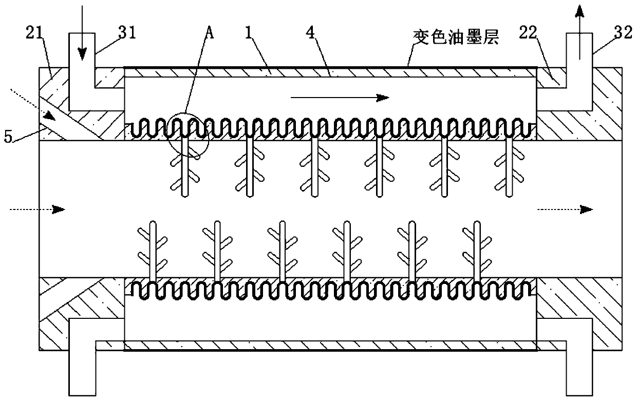
[0051] S3. Under the action of multiple sets of internal heat-reducing bifurcation rods and cooling liquid in the conveying device, double heat-reducing of combustible gas is achieved for safe conveying;

[0052] S4. Through the color change on the surface of the conveying device, the temperature regulation of the cooling liquid is realized during the conveying process;

[0053] S5. After the combustible gas undergoes double cooling, it is in a low-temperature state and is continuously transported in the transport device.

[0054] The clear air gas is ...

Embodiment 2

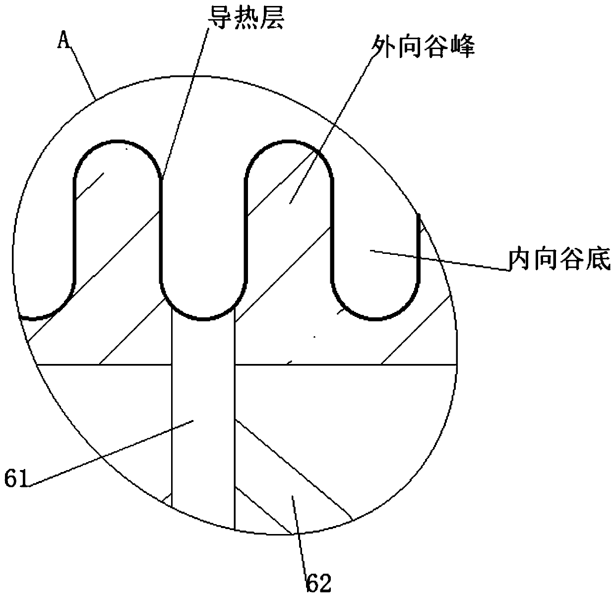
[0059] The inward valley bottom can be set as a special-shaped structure with a wide bottom and a narrow mouth. A water-repellent lodging rod is placed in the inward valley bottom. When the coolant is introduced, the water-repellent lodging rod can swing left and right in the inward valley bottom, thereby accelerating the inward valley bottom. The fluidity of the coolant improves the absorption efficiency of the coolant for this part of the heat, thereby accelerating the reduction of the overall heat of the combustible gas. The water-repellent lodging rod includes a swing fulcrum ball 7 placed inward toward the bottom of the valley, and the upper end of the swing fulcrum ball 7 is fixedly connected. There is an elastic lodging main rod 8, and the ends of the elastic lodging main rod 8 are fixedly connected with a plurality of flexible water-repelling rods 9. When the water-repelling and lodging rods swing left and right with the cooling liquid, the elastic lodging main rods 8 co...


PUM


Abstract

The invention discloses a method and device for conveying combustible gas generated in leachate treatment, and belongs to the technical field of combustible gas conveying. By means of the method and device for conveying combustible gas generated in leachate treatment, by introducing emptying gas into a cooling conveying pipe in the conveying process, the concentration of the combustible gas can beeffectively reduced, and the spontaneous combustion and explosion probability in the conveying process of the combustible gas is reduced; meanwhile, after the combustible gas is introduced into the cooling conveying pipe, cooling liquid can effectively absorb the heat in the combustible gas from the outside, and meanwhile an inner cooling headtree makes direct contact with the combustible gas andcan cool the combustible gas from the inside, so the heat carried by the combustible gas can be remarkably reduced under the inside and outside duplex action, and then the spontaneous combustion or explosion caused by the high heat in the conveying process of the combustible gas is effectively reduced, and the conveying safety of the combustible gas generated in waste incineration is effectivelyimproved.

Description

technical field [0001] The invention relates to the technical field of combustible gas transportation, and more specifically, relates to a method and device for conveying combustible gas produced by leachate treatment. Background technique [0002] Waste incineration is the process of reducing the volume of waste through oxidation at high temperature through appropriate thermal decomposition, combustion, melting and other reactions, and turning it into residue or molten solid matter. Waste incineration facilities must be equipped with flue gas treatment facilities to prevent heavy metals and organic pollutants from being discharged into the environmental medium again. Recycling the heat generated by garbage incineration can achieve the purpose of recycling waste. [0003] Garbage incineration is an older and traditional method of garbage disposal. After the garbage is treated by incineration, the reduction effect is remarkable, the land is saved, and various pathogens can b...

Claims


Application Information

Patent Timeline
Patent Type & Authority Applications(China)
IPC IPC(8): F16L53/70F17D5/00
CPCF16L53/70F17D5/00
Inventor 黄春华陈鑫周挺朱黄磅梁超李伟叶锦瑜
Owner 瀚蓝(福清)固废处理有限公司
Why Eureka
Try Eureka