
Display

A display and display area technology, applied in the direction of instruments, optics, cameras, etc., can solve problems such as difficulty in setting

Active Publication Date: 2011-02-23
AU OPTRONICS CORP
View PDF4 Cites 5 Cited by
  • Summary
  • Abstract
  • Description
  • Claims
  • Application Information

AI Technical Summary

Problems solved by technology

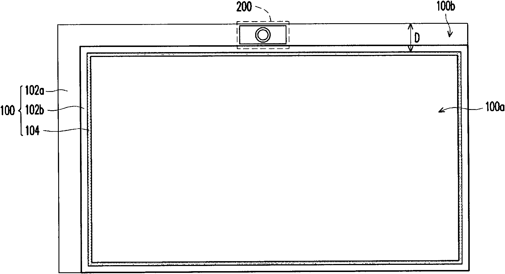
[0004] However, as users have higher and higher requirements on the appearance of the display panel 100, the width D of the peripheral area 100b of the display panel 100 must also be narrowed accordingly. Difficulty setting up on zone 100b

Method used


Image

  • Display
  • Display
  • Display

Examples


Embodiment Construction

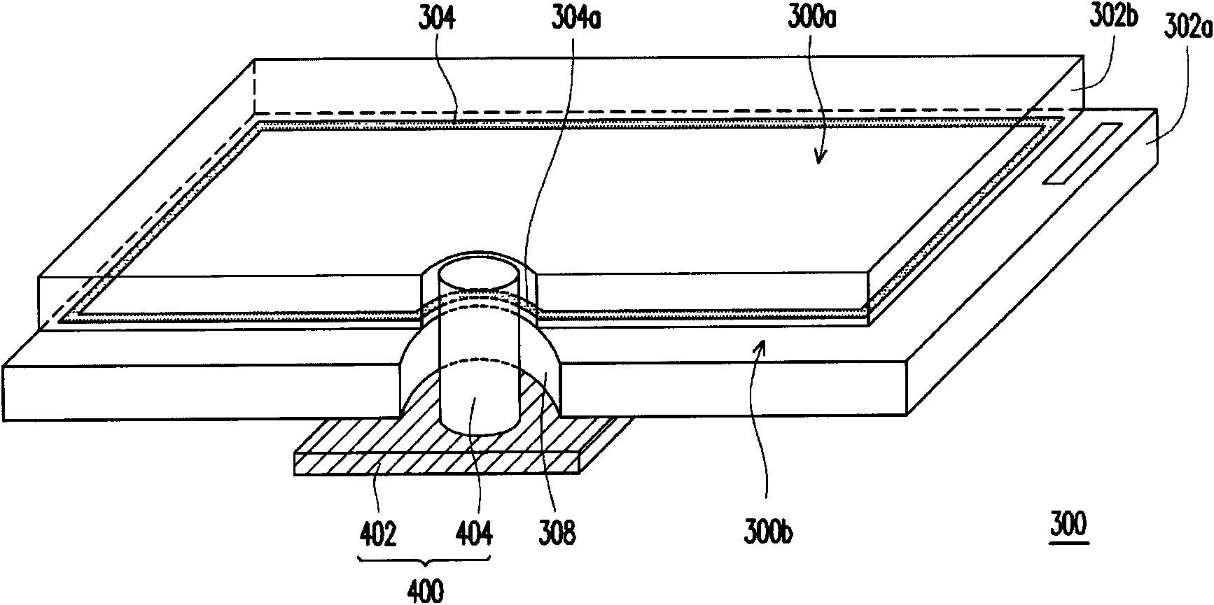
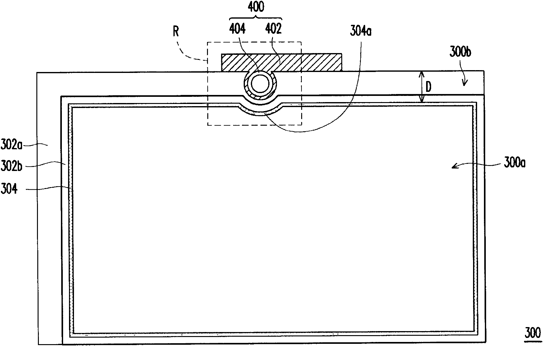
[0041] Figure 2A It is a three-dimensional schematic diagram of a display according to an embodiment of the present invention. Figure 2B for Figure 2A top view diagram. and image 3 , Figure 4A to Figure 4J as well as Figure 5 for Figure 2B An enlarged schematic view of the local region R of .

[0042] Please refer to Figure 2A The display in this embodiment includes a display panel 300 and an image capture device 400, wherein the display panel 300 includes a first substrate 302a, a second substrate 302b, a sealant 304, and a display medium (not shown).

[0043] In this embodiment, the first substrate 302a is, for example, an active device array substrate. Specifically, the first substrate 302a is, for example, a thin film transistor array substrate, and the thin film transistor array substrate has a plurality of scanning lines (not shown), a plurality of data lines (not shown), a plurality of thin film transistors (not shown). shown) and a plurality of pixel u...


PUM


Abstract

The invention discloses a display, which comprises a display panel and an image acquisition device, wherein the display panel is provided with a display area, a peripheral area enclosing the display area and a through hole positioned in the peripheral area; the image acquisition device is assembled on the display panel, and comprises a signal transmission element and an image acquisition element positioned in the through hole; and the image acquisition element is connected with the signal transmission element.

Description

technical field [0001] The present invention relates to a display, and in particular to a display with an image capture device. Background technique [0002] Today, with the development of information, electronic information equipment, such as notebook computers, desktop computers, monitors, and televisions, has become one of the indispensable electronic products in modern people's life. With the development of technology, it is a mature technology to integrate the image capture device on the display panel of the aforementioned electronic information equipment. The image capture device can allow the user to interact with the remote user, Or it can be used to record personal audio-visual images. [0003] figure 1 It is a schematic top view of an existing display panel. Please refer to figure 1 The display panel 100 includes a first substrate 102a, a second substrate 102b, and a sealant 104 between the first substrate 102a and the second substrate 120b. In the display pan...

Claims


Application Information

Patent Timeline
IPC IPC(8): G09F9/00G03B29/00
Inventor 萧毅豪谢文章
Owner AU OPTRONICS CORP
Learn More