Imaging device, imaging module, electronic still camera, and electronic movie camera

A camera device and pixel technology, applied to static cameras, signal generators with a single pick-up device, TV, etc., can solve problems such as lower resolution, larger camera system, and image quality deterioration

Inactive Publication Date: 2011-02-23
PANASONIC CORP
View PDF2 Cites 9 Cited by
  • Summary
  • Abstract
  • Description
  • Claims
  • Application Information

AI Technical Summary

Problems solved by technology

[0007] However, when pixel blending is performed as in the aforementioned Patent Document 1, since the shape of the pixel blending becomes an oblique direction, the LPF is inevitably involved in the vertical direction and the horizontal direction, resulting in deterioration of resolution.
In addition, since the shape of pixel blending has anisotropy with respect to the oblique direction, it is necessary to eliminate the anisotropy by image processing, but applying such processing will make the resolution deterioration more noticeable
[0008] In addition, in the pixel mixing shown in Patent Document 2, since the center of gravity of the pixel after pixel mixing is related to the pixel misalignment, the degradation of resolution can be reduced. However, since the pixel itself has a modulation component due to a color filter, It is practically difficult to significantly increase the resolution
In addition, since multiple pixels are mixed in two dimensions, a large number of pixels are actually required to output high-definition moving images, resulting in an increase in the size of the imaging system or a decrease in image quality due to the miniaturization of the pixel size of the image sensor. deterioration

Method used


Image

  • Imaging device, imaging module, electronic still camera, and electronic movie camera
  • Imaging device, imaging module, electronic still camera, and electronic movie camera
  • Imaging device, imaging module, electronic still camera, and electronic movie camera

Examples


Embodiment approach 1

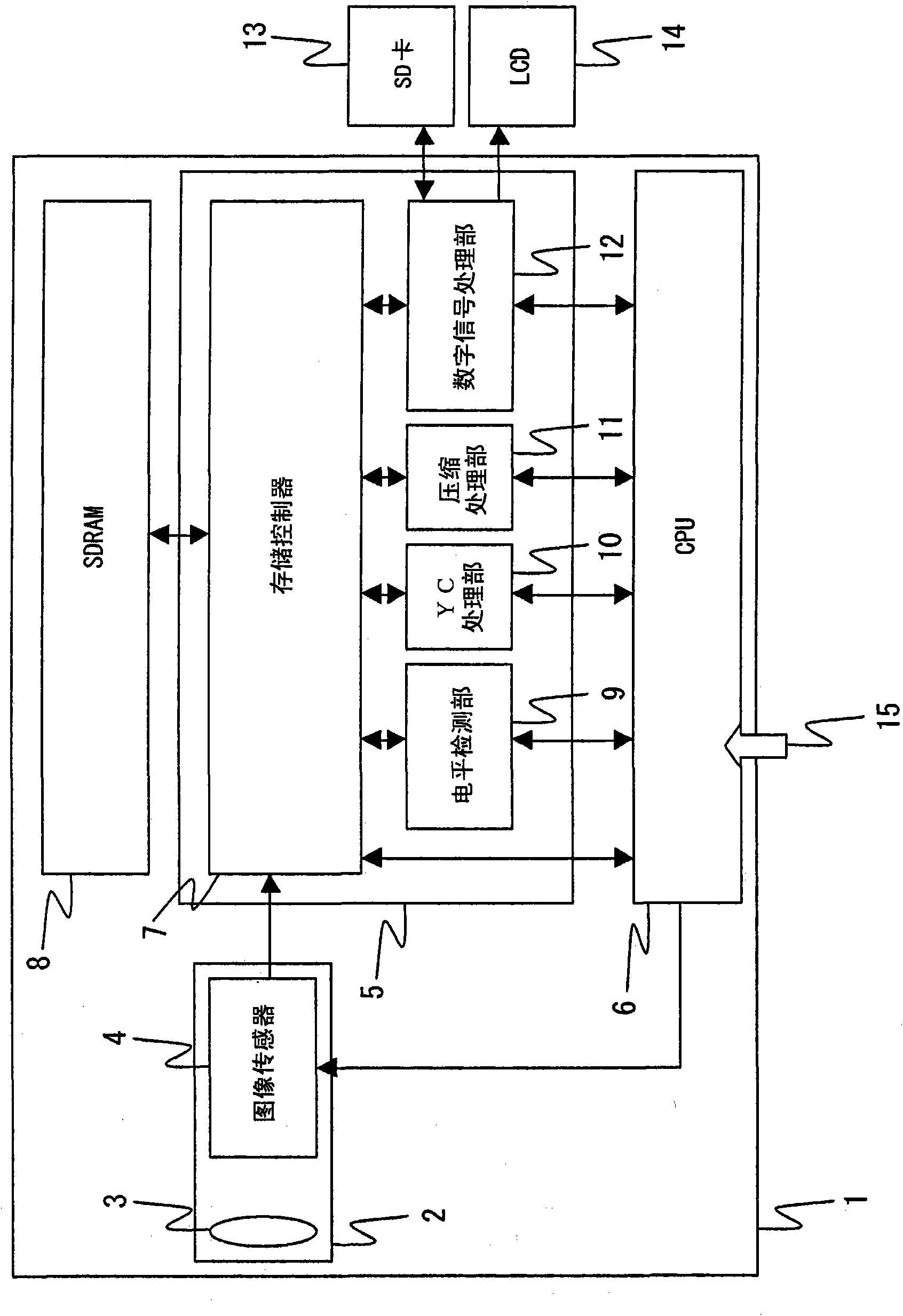
[0104] Hereinafter, the imaging system in Embodiment 1 of the present invention will be described. figure 1 It is a block diagram which shows the functional structure of the imaging system in this embodiment. The imaging system in this embodiment is constituted by a digital video camera 1 (electronic dynamic camera), which includes an imaging module 2 , a DSP 5 , a CPU (Central Processing Unit) 6 , and an SDRAM 8 .

[0105] (Configuration of camera module 2)

[0106] The camera module 2 has a lens 3 and an image sensor 4 . In addition, although not shown, the camera module 2 further includes a TG (timing generator) for generating a control signal necessary for driving the image sensor 4 .

[0107] (DSP and SDRAM)

[0108] The DSP 5 includes a memory controller 7 , a level detection unit 9 , a YC processing unit 10 , a compression processing unit 11 , and a digital signal processing unit 12 . The DSP 5 processes the output from the image sensor 4 .

[0109] The memory cont...

Embodiment approach 2

[0197] Here, the imaging system in Embodiment 2 of the present invention will be described. The imaging system in Embodiment 2 of the present invention is a part of the configuration of Embodiment 1 of the present invention that has been changed, and the following description will start from the difference.

[0198] (Image sensor driver and column control section)

[0199] A method of driving the image sensor 4 will be described.

[0200] This embodiment is equivalent to Embodiment 1, and the difference only relates to the case where pixel signals are mixed and read in the column direction, and only this part will be described here.

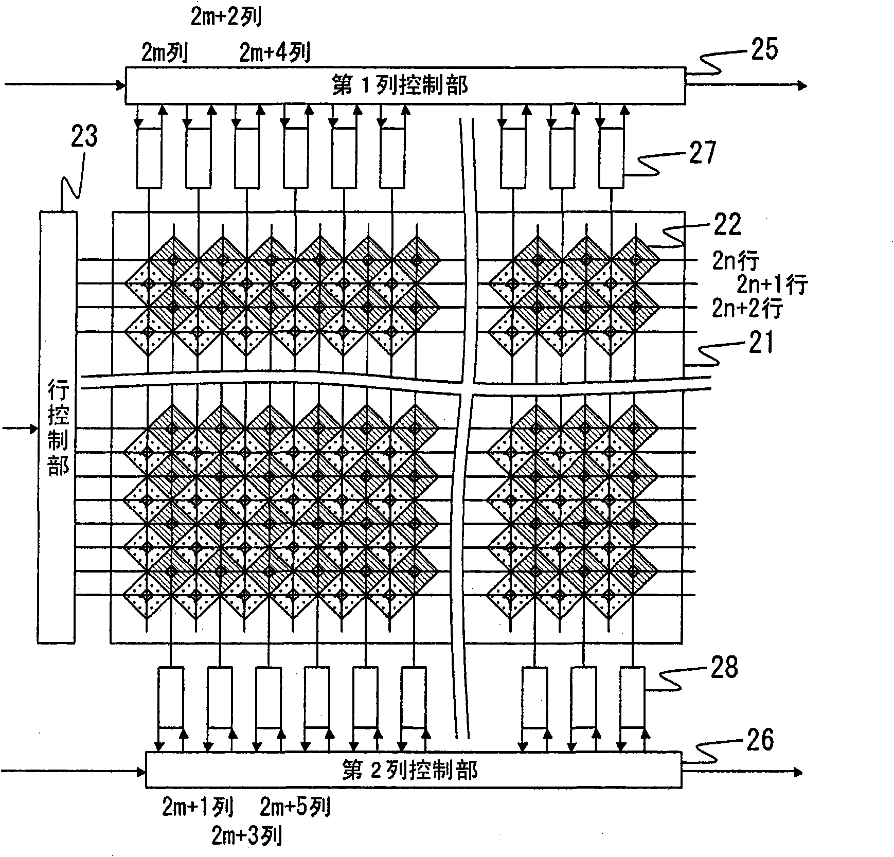
[0201] After the exposure of the pixels 22 for a predetermined exposure time is completed, the row control unit 23 outputs a row selection signal for executing the reading of the imaging signal for the pixels 22 in the 2nth row. Based on the row selection signal, it is determined to read the imaging signal stored in the pixel 22 of the 2nth row...

Embodiment approach 3

[0216] Here, the imaging system in Embodiment 3 of the present invention will be described. The imaging system in Embodiment 3 of the present invention is a part of the configuration of Embodiment 1 of the present invention that has been changed, and the following description will start from the difference.

[0217] -Image sensor driver and column control section-

[0218] Hereinafter, a method of driving the image sensor 4 will be described.

[0219] The difference between this embodiment and Embodiment 1 only relates to the case where pixel signals are mixed and read in the column direction, and only this part will be described here.

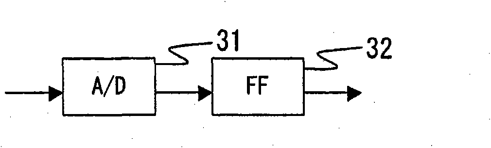
[0220] In the present embodiment, the configuration and operation method of the first column control unit 25 are different. The first column control unit 25 of the present embodiment has the following Figure 14 composition shown. The first column control unit includes a selector 1441, an adder 1442, a selector 1443, and a flip-flop 1444 (...


PUM


Abstract

An imaging device includes: a plurality of pixels (22) which output a pixel signal obtained by photoelectrically converting an incident light; and pixel mixing units (25, 26, 27, 28) which mix pixel signals from pixels of adjacent rows. The pixel mixing units (25, 26, 27, 28) perform a first pixel mixing operation which mixes pixel signals in the same columns and a second pixel mixing operation which mixes pixel signals in the same rows.

Description

technical field [0001] The present invention relates to an imaging device having a plurality of pixels arranged in shifted positions and mixing and reading the pixels, an imaging module using the imaging device, an electronic still camera, and an electronic dynamic camera. Background technique [0002] In an imaging device composed of a plurality of pixels arranged in shifted positions, as a technique for improving the speed or sensitivity of reading pixel signals from the imaging device, for example, there is a technique of mixing pixels to read (for example, see Patent Document 1, Patent Document 2). [0003] Patent Document 1 discloses a method of alternately and repeatedly forming pixel rows in which green pixels and magenta pixels are alternately arranged and pixel rows in which cyan pixels and yellow pixels are alternately and repeatedly arranged, and The pixel addition is performed for the green pixel and the cyan pixel or the yellow pixel, and the pixel addition is ...

Claims


Application Information

Patent Timeline
IPC IPC(8): H04N5/335H04N5/347H04N5/374H04N101/00H04N5/349H04N9/07
CPCH04N2101/00H04N2209/045H04N9/045H04N25/46
Inventor 今村邦博藤井俊哉松长诚之
Owner PANASONIC CORP
Why Eureka
Try Eureka