Illumination fixture
A technology for lighting fixtures and appliances, which is applied in the direction of lighting devices, fixed lighting devices, lighting auxiliary devices, etc., can solve problems such as misoperation of lighting fixtures, achieve the effects of improving assembly performance and suppressing temperature rise
- Summary
- Abstract
- Description
- Claims
- Application Information
AI Technical Summary
Problems solved by technology
Method used
Image
Examples
Embodiment approach 1
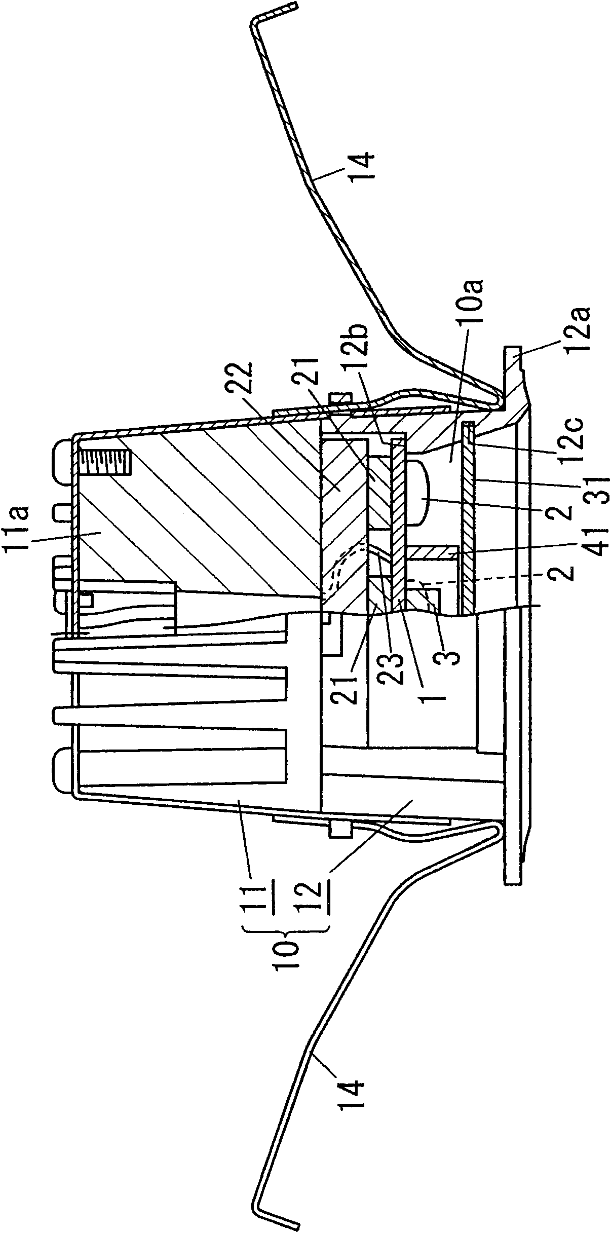
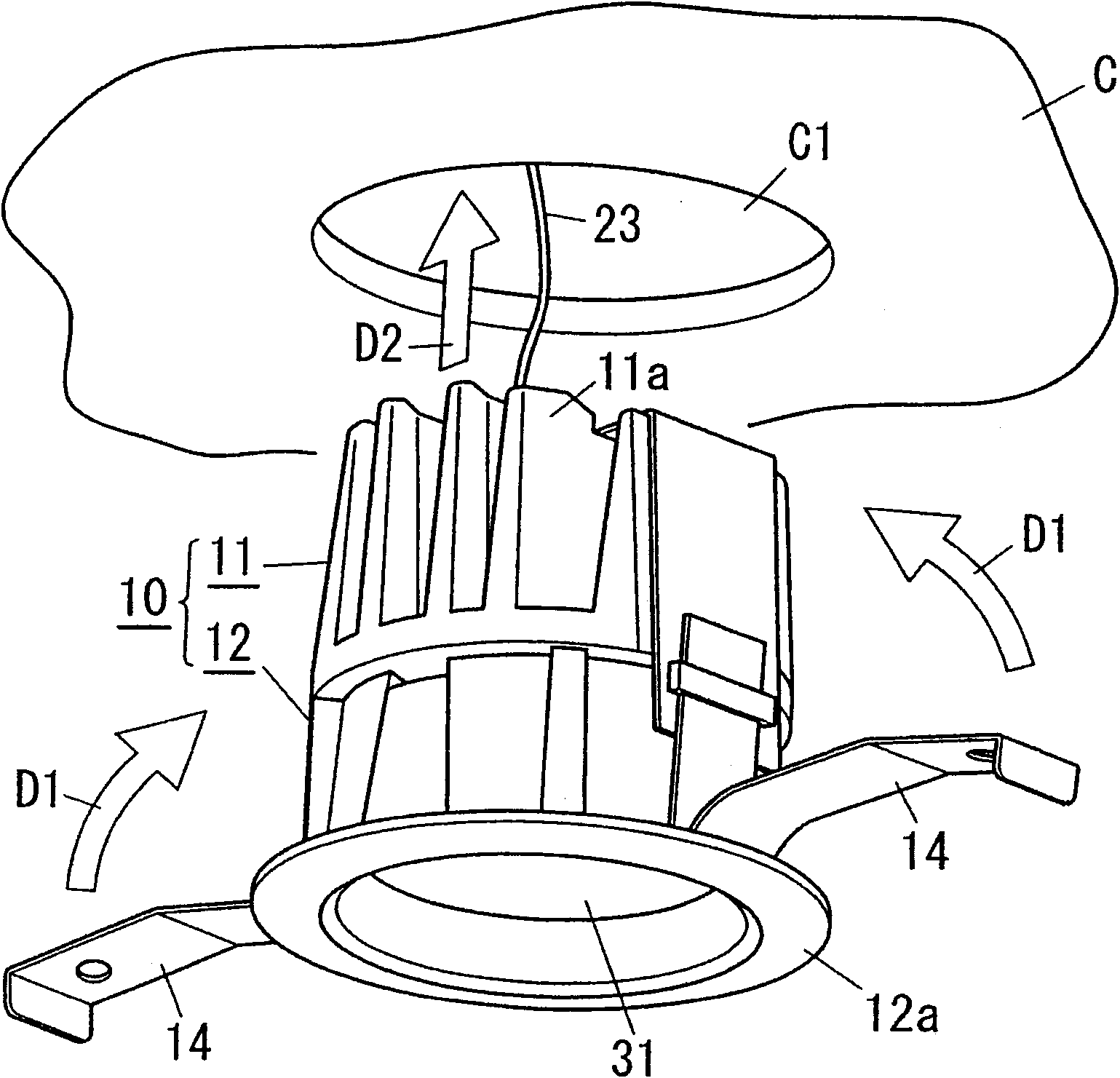
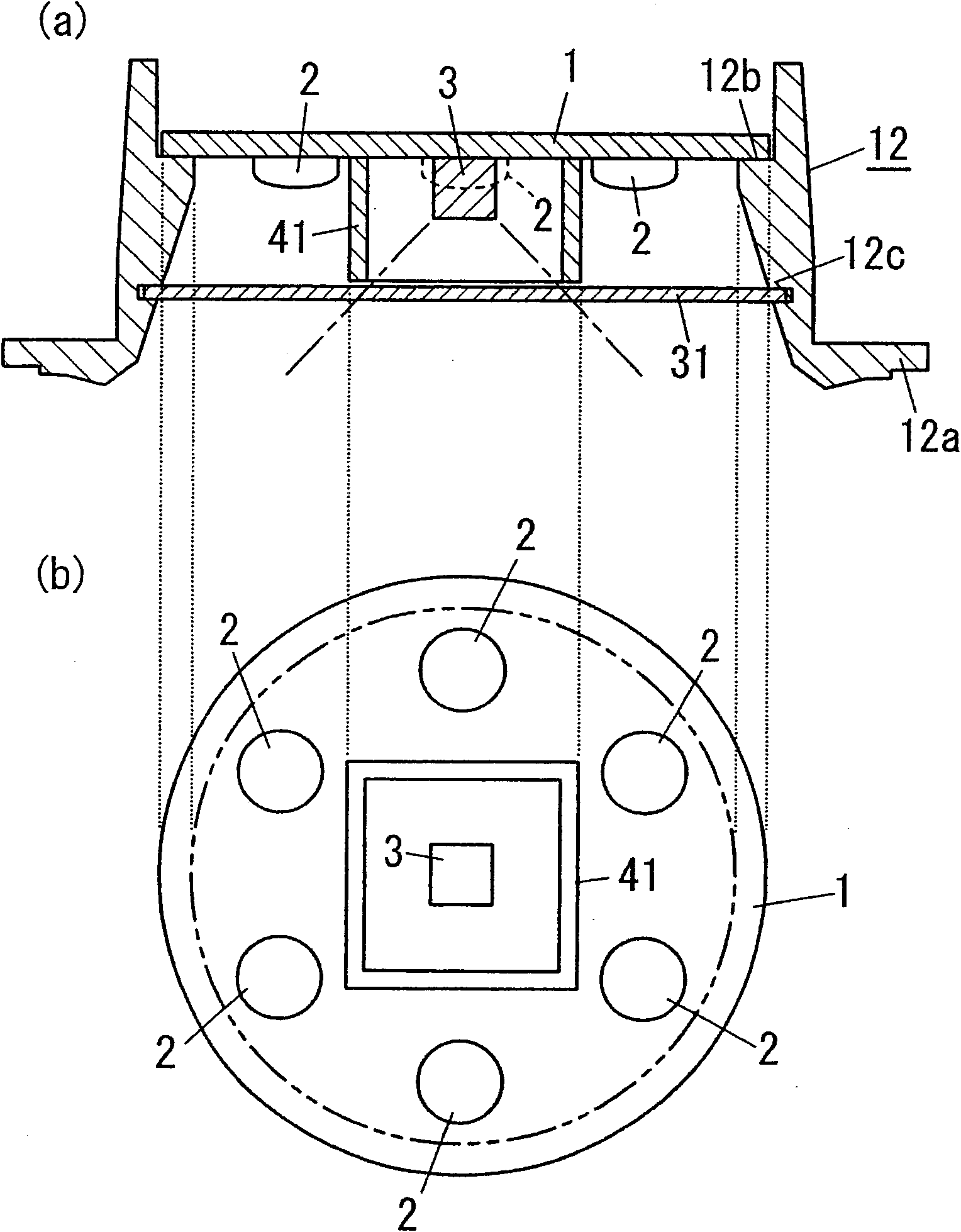
[0053] according to Figure 1 to Figure 4 This embodiment will be described.
[0054] The lighting fixture of this embodiment is a ceiling-embedded LED lighting fixture, and includes: a plurality of (in image 3 In the example shown, 6) the light emitting part 2 is constituted by a light emitting element using an LED chip, that is, an LED element (not shown); the sensor part 3 (refer to image 3 ) has an infrared sensor element that detects infrared rays emitted from the human body; the lighting device (not shown) has a control circuit part (not shown) as a control unit, and the control circuit part is based on the output of the sensor part 3. The power supplied to the light emitting unit 2 is controlled to turn on and off the light emitting unit 2 ; and the device main body 10 has the light emitting unit 2 and the sensor unit 3 disposed therein. Furthermore, the lighting fixture according to this embodiment includes: a base substrate 1 formed in a circular plate shape in pl...
Embodiment approach 2
[0071] The lighting fixture of this embodiment is such as Figure 5 As shown, similarly to Embodiment 1, there is an opening 10a for the device main body 10 to take out visible light emitted from the light emitting unit 2 to the outside, and a translucent panel 32a is arranged to cover the opening 10a. On the other hand, the lighting fixture of this embodiment differs from Embodiment 1 in that the partition wall 41 is integrally formed continuously with the translucent panel 32a. In addition, the same code|symbol is attached|subjected to the same structure as Embodiment 1, and description is abbreviate|omitted.
[0072] The light-transmitting panel 32a is formed into a disc shape, and a through-hole 32c is provided through the central part, and the partition wall 41 is integrally formed with the periphery of the through-hole 32c of the light-transmitting panel 32a. One surface side of the direction protrudes. Here, the light-transmitting panel 32a and the partition wall 41 a...
Embodiment approach 3
[0076] Such as Figure 6 As shown in (a), the difference between the lighting fixture of this embodiment and Embodiment 1 is that the lighting fixture of this embodiment includes: a first base substrate 1 a formed in a disk shape, and a through hole is formed through the center portion. 1aa; and the second base substrate 1b, which is formed in a disk shape, has an outer shape smaller than the through hole 1aa, and is arranged inside the through hole 1aa; the light emitting part 2 is mounted on the first base substrate 1a, and the second base The sensor unit 3 is mounted on the substrate 1b, and the partition wall 41 holds the second base substrate 1b and is mounted on the first base substrate 1a. In addition, the same code|symbol is attached|subjected to the same structure as Embodiment 1, and description is abbreviate|omitted.
[0077] here, as Figure 6 As shown in (b), the partition wall 41 is formed of a material (for example, acrylic resin) whose transmittance is higher...
PUM
 Abstract
Description
Claims
Application Information
 - R&D
- Intellectual Property
- Life Sciences
- Materials
- Tech Scout
- Unparalleled Data Quality
- Higher Quality Content
- 60% Fewer Hallucinations
Browse by: Latest US Patents, China's latest patents, Technical Efficacy Thesaurus, Application Domain, Technology Topic, Popular Technical Reports.
© 2025 PatSnap. All rights reserved.Legal|Privacy policy|Modern Slavery Act Transparency Statement|Sitemap|About US| Contact US: help@patsnap.com


