Sealing device for eliminating gaps between traverse baffles and shell of shell and tube heat exchanger

A tube-and-tube heat exchanger and sealing device technology, which is applied in the direction of heat exchanger casing, engine sealing, heat exchange equipment, etc., can solve the problem of shell side fluid short circuit, failure to reach temperature, fluid short circuit is not effectively controlled, etc. problem, achieve the effect of improving heat exchange efficiency and preventing short circuit phenomenon

Inactive Publication Date: 2011-03-16
镇江飞利达电站设备有限公司
View PDF5 Cites 6 Cited by
  • Summary
  • Abstract
  • Description
  • Claims
  • Application Information

AI Technical Summary

Problems solved by technology

Considering the convenience of assembly, maintenance and cleaning of the tube-and-tube heat exchanger, there is generally a certain installation gap between the shell and the baffle, and there is a certain gap between the limited circle of the tube arrangement and the inner wall of the shell, so This causes the short-circuit phenomenon of the shell-side fluid in the normal use of the shell-and-tube heat exchanger in parallel and perpendicular to the flow direction of the heat transfer tube, which affects the heat transfer effect of the shell-and-tube heat exchanger, and ultimately fails to meet the design requirements. temperature
[0003] In order to solve the shell-side fluid short-circuit problem of the shell-and-tube heat exchanger, Article 5.13 of GB151-1999 "Shell-and-Tube Heat Exchanger" has proposed bypass baffles, The baffle tube and the intermediate baffle are three measures to prevent the short circuit of the fluid on the shell side, but the existing short circuit structure only controls the short circuit of the fluid on the shell side perpendicular to the flow direction of the tube bundle, and does not prevent the short circuit of the fluid parallel to the flow direction of the tube bundle. be effectively controlled

Method used


Image

  • Sealing device for eliminating gaps between traverse baffles and shell of shell and tube heat exchanger
  • Sealing device for eliminating gaps between traverse baffles and shell of shell and tube heat exchanger
  • Sealing device for eliminating gaps between traverse baffles and shell of shell and tube heat exchanger

Examples


Embodiment Construction

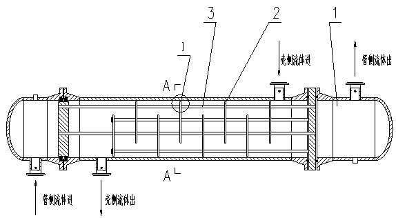
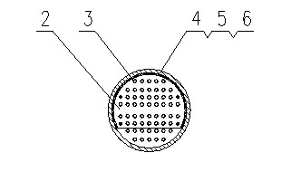
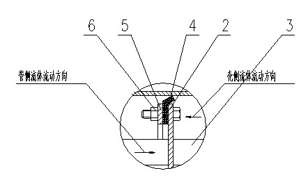
[0021] refer to figure 1 , figure 2 , image 3 , the present invention is a sealing device for eliminating the gap between the baffle plate and the shell of the tube-and-tube heat exchanger, which includes a baffle plate 2 and a fastener 6, and is characterized in that the semicircular edge of the baffle plate is provided with An annular sealing strip 4 with an L-shaped fold, and an annular pressure strip 5 that is equal in length and matches the annular sealing strip is arranged on one side of the annular sealing strip.

[0022] In the specific manufacturing process, firstly, the inner and outer diameters and thicknesses of the annular sealing strip 4 and the annular bead 5 in the sealing device are determined according to the inner diameter of a certain shell, the outer diameter of the baffle plate and the diameter of the pipe limiting circle. The annular sealing strip is made by mold and molded; the annular bead is processed by blanking, turning and drilling. The annula...


PUM


Abstract

The invention discloses a sealing device for eliminating gaps between traverse baffles and a shell of a shell and tube heat exchanger, which comprises the traverse baffles and fastening parts. The sealing device is characterized in that: the semicircular edge part of the traverse baffle is provided with an annular sealing strip with an L-shaped edgefold; and one side of the annular sealing strip is provided with an annular trim strip which is as long as and matched with the annular sealing strip. The sealing device prevents a fluid from taking a shortcut from the mounting spaces between the semicircular edge parts of the traverse baffles and the shell of the heat exchanger to force the fluid to completely flow in an S-shaped curve under the guidance of the traverse baffles; therefore, full heat exchange can be realized between the fluids on tube sides and the shell side, and the heat exchange effect is remarkably bettered under the same working conditions.

Description

technical field [0001] The invention relates to a sealer for eliminating the gap between the baffle plate and the shell of the tube-and-tube heat exchanger, in particular to a sealing device for eliminating the gap between the baffle plate and the shell of the tube-and-tube heat exchanger. Background technique [0002] In order to ensure that the fluid in industrial production can operate normally at the rated temperature, a heat exchanger must be used to exchange heat for the fluid. Tube and tube heat exchangers are generally used now. The shell and tube heat exchanger is composed of tube box, shell, tube plate, baffle plate, tube bundle, connecting pipe and flange. The purpose of installing baffles is to increase the flow velocity of the shell-side fluid and continuously change the flow direction of the fluid to intensify the degree of turbulence, so as to improve the convective heat transfer coefficient of the shell-side fluid. Considering the convenience of assembly, m...

Claims


Application Information

Patent Timeline
Patent Type & Authority Applications(China)
IPC IPC(8): F28F9/00F16J15/06
Inventor 莫纪洪黄永福何兴生戴正军
Owner 镇江飞利达电站设备有限公司
Why Eureka
Try Eureka