Combined power and refrigeration cycle system of absorption steam turbine

A circulation system and steam turbine technology, applied in the direction of adsorption machines, steam engine devices, refrigerators, etc., can solve the problems of large amounts of electric energy and cooling capacity, unsatisfactory economy, environmental heat pollution, etc. in fertilizer plants, and achieve waste heat utilization process and The equipment is simple, conducive to popularization and implementation, and the effect of low implementation cost

Inactive Publication Date: 2010-10-27
ZHENGZHOU UNIV
View PDF6 Cites 5 Cited by
  • Summary
  • Abstract
  • Description
  • Claims
  • Application Information

AI Technical Summary

Problems solved by technology

[0002] There are a lot of heat sources or waste heat below 150°C in our society. It is economically uneconomical for this part of heat to be used for power generation. It is used for refrigeration because its thermal coefficient is low and economically unsatisfactory. Most of it is discharged into the environment. heat pollution to the environment
For example, when a fertilizer plant produces synthetic ammonia, a large amount of waste heat at 150°C will be discharged into the environment. At the same time, the fertilizer plant requires a large amount of electric energy and cooling capacity. The waste of energy and the ineffective use of energy have become obstacles to the further development of enterprises.

Method used


Image

  • Combined power and refrigeration cycle system of absorption steam turbine
  • Combined power and refrigeration cycle system of absorption steam turbine
  • Combined power and refrigeration cycle system of absorption steam turbine

Examples


Embodiment 1

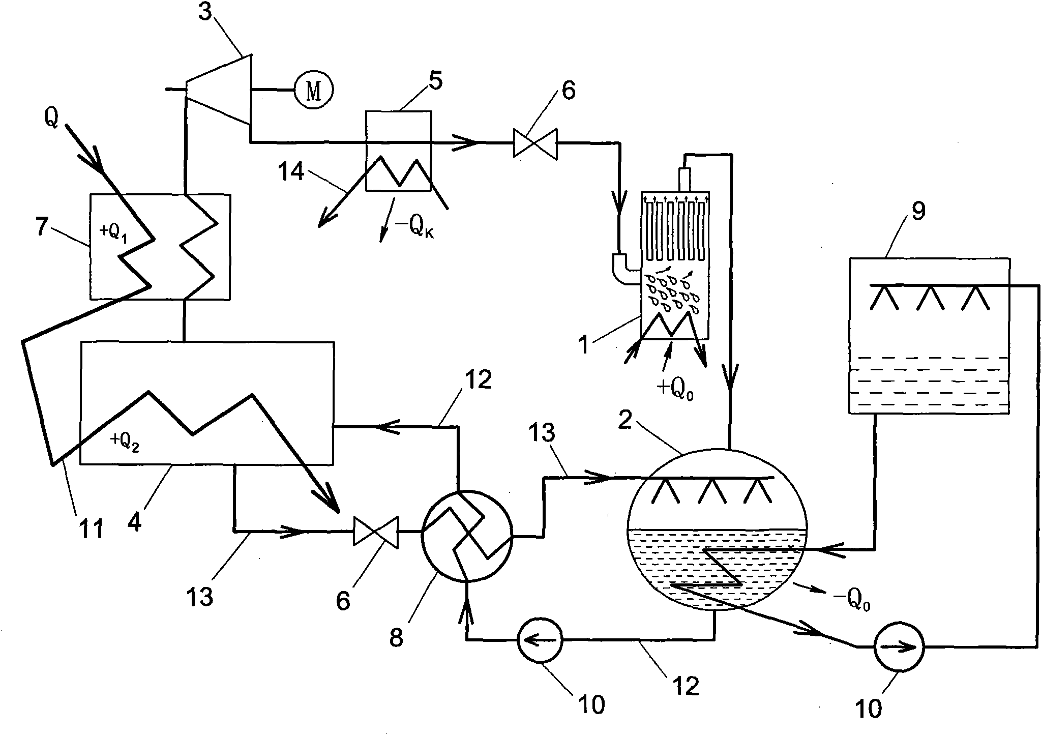
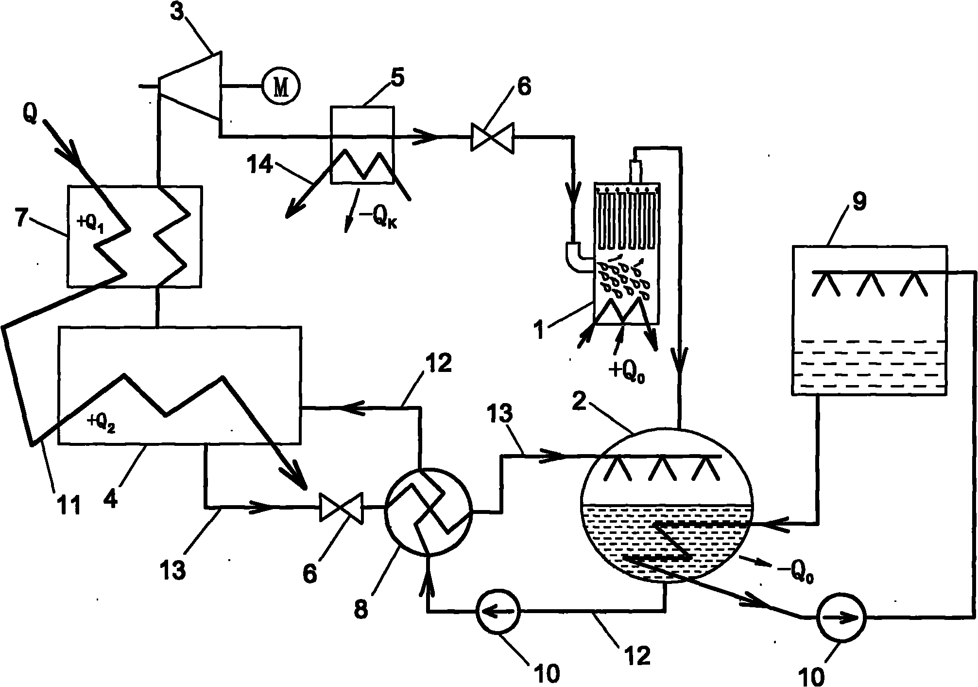
[0021] Example 1: see figure 1 , An absorption steam turbine power-cooling mixed cycle system, including an evaporator 1, an absorber 2, a steam turbine 3, a generator 4, a condenser 5 and a throttle valve 6, etc. In this embodiment, waste heat is used to heat the mixed working fluid, such as lithium bromide solution, and the steam generated after passing through the generator can drive the steam turbine to perform work. In the evaporator, the refrigerant absorbs heat and evaporates to produce cold energy.

[0022] The specific implementation is that the waste heat pipe 11 is in communication with the heat inlet of the heat exchanger of the generator 4, and the mixed working fluid is heated by the waste heat in the generator 4, the temperature rises, and the heat Q of the waste heat is absorbed. 2 (The + or-signs in the figure only indicate the absorption or release of heat), where the light floating working fluid is vaporized into hot steam, the steam outlet of the generator 4 pas...

Embodiment 2

[0025] Embodiment 2: The drawings are not drawn, and the content is basically the same as that of Embodiment 1. The similarities are not repeated. The difference is that the outlet of the concentrated solution of the generator is connected to the inlet of the absorber through a throttling tube.

Embodiment 3

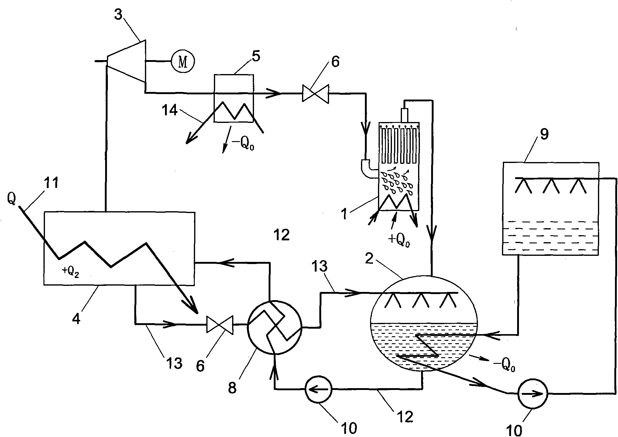
[0026] Example three: see figure 2 , The content is basically the same as the first embodiment, and the similarities are not repeated. The difference is: the steam in the generator directly drives the steam turbine to do work through the pipeline, and there is no superheater in the middle.


PUM


Abstract

The invention relates to a combined power and refrigeration cycle system of an absorption steam turbine, which comprises a steam turbine, an evaporator, an absorber and a generator. The steam outlet of the evaporator is communicated with the steam inlet of the absorber. The dilute solution outlet pipe of the absorber is communicated with the solution inlet of a water pump. The water pump pressurizes the dilute solution and delivers the dilute solution to the solution inlet of the generator. The concentrated solution outlet of the generator is communicated with the solution inlet of the absorber after being throttled. A waste heat pipe is communicated with the heat inlet of the heat exchanger of the generator supplies heat to the generator. The steam outlet of the generator is communicated with the steam inlet of the steam turbine. The steam turbine does work. The exhaust port of the steam turbine is communicated with the inlet of the evaporator sequentially through a condenser and a throttle valve. The invention has the advantages that the waste heat is used for generating power which is used as power compensation and the power supplied by the grid is reduced; a great quantity of refrigeration energy can be provided for cooling in factories, the electric energy used for refrigeration in the factories is reduced, the double benefits are obtained, the environment is protected and the energy is saved; and the implementation cost is low, the effect is obvious and the popularization and the implementation are greatly facilitated.

Description

1. Technical Field: [0001] The invention relates to a waste heat utilization technology, in particular to an absorption steam turbine power-cooling mixed circulation system. 2. Background technology: [0002] There are a large number of heat sources or waste heat less than 150℃ in our society. This part of heat is not economically economical for power generation, and its thermal coefficient is low for cooling, which is economically unsatisfactory. Most of it is discharged into the environment. Cause thermal pollution to the environment. For example, when a chemical fertilizer plant produces synthetic ammonia, a large amount of waste heat of 150°C is discharged into the environment. At the same time, the chemical fertilizer plant requires a large amount of electricity and cooling. The waste of energy and the ineffective use of energy have become obstacles to the further development of enterprises. 3. Summary of the invention: [0003] The invention overcomes the shortcomings of th...

Claims


Application Information

Patent Timeline
Patent Type & Authority Applications(China)
IPC IPC(8): F01K27/00F01K11/02F01D15/10F25B27/02F25B15/06
CPCY02B30/625Y02A30/274Y02P80/15
Inventor 王海峰王舟
Owner ZHENGZHOU UNIV
Why Eureka
Try Eureka